Switching issues
- Thread starter Rampz
- Start date
hippy
Ex-Staff (retired)
Possibly, though it might be better described as getting bogged-down in minutiae, premature optimisation, fretting over things which aren't worth worrying about at this stage of the project, trying to address problems you may not have.but am i over complicating the issue
When a project has too much to it, it can stall under its own weight, becomes too diverse or complicated to be handled. What one wants to do gets held back back by 'how one will do it' sub-projects, which may turn out to have been unnecessary.
The traditional development approach is to prototype in a perfect environment to get what's wanted done and proven to work, and then commission that and resolve any issues which may exist in the deployed environment.
One would normally also simplify the prototype, get that working, then expand it. For a display which reports data from two devices, those devices don't need to be the real devices, can be substituted by something which sends fixed or simplified data. We don't care what that data is as we are merely trying to get the protocol working, getting data displayed. Get that working then figuring out how real devices would implement what's needed is an incremental step on top of that.
Of course there are projects where everything needs to defined before anything can be implemented. But those are often the expensive ones which over run their budgets and timescales and quite often don't deliver anything at all.
Rampz
Well-known member
Thank you Hippy, i was trying to follow the idea with this to define what was the minimum needed right at the start, work out the best picaxe etc rather than keep re-engineering, but you're right get something working and go from there.Possibly, though it might be better described as getting bogged-down in minutiae, premature optimisation, fretting over things which aren't worth worrying about at this stage of the project, trying to address problems you may not have.
When a project has too much to it, it can stall under its own weight, becomes too diverse or complicated to be handled. What one wants to do gets held back back by 'how one will do it' sub-projects, which may turn out to have been unnecessary.
The traditional development approach is to prototype in a perfect environment to get what's wanted done and proven to work, and then commission that and resolve any issues which may exist in the deployed environment.
One would normally also simplify the prototype, get that working, then expand it. For a display which reports data from two devices, those devices don't need to be the real devices, can be substituted by something which sends fixed or simplified data. We don't care what that data is as we are merely trying to get the protocol working, getting data displayed. Get that working then figuring out how real devices would implement what's needed is an incremental step on top of that.
Of course there are projects where everything needs to defined before anything can be implemented. But those are often the expensive ones which over run their budgets and timescales and quite often don't deliver anything at all.
So will start the task of getting a DS3231 and a 28X2 directly driving an 4 line OLED screen showing the time and see how it goes.
Just reading about driving the screen, seems it can be 4-bit or 8-bit any advantages over either? looks in a basic way, 4-bit = 4 pins and 8-bit = 8 pins, maybe 4-bit takes longer to send data? still reading
Phil, i don't know anything about 20ma current loop, but will look it up, like Hippy says i am looking for solution for problems i haven't encountered yet, i'm trying to cover all aspects, i guess its finding the easiest way to communicate, this being an area i have no great understanding yet
")
Yep i can see what you mean Phil, this is the 5ma current loop its a whole new thing, ok 54 years late, question being in my application is it a good idea? seems 20ma loop can run 2000ft at 19.2k, i'm only wanting to flash an led 10 ft away maximum at a suitable speed
Last edited:
lbenson
Senior Member
Exactly which OLED? There are many examples on the forum. 8-bit will update faster than 4-bit, but it's a rare case where that speed would make a difference to a human viewer. 8-bit has less software complexity, but if you're copying existing code (as I have done in all cases with displays on picaxes), it doesn't much matter--hippy and others have led the way.28X2 directly driving an 4 line OLED screen showing the time and see how it goes
Rampz
Well-known member
Ibenson the OLED is the one that comes as part number AXE134Y from the picaxe store, 8-bit sounds fine anything to keep the code more simple etc, as long as can still use the other pins like i will need for the clock module, hserin and hserout etcExactly which OLED? There are many examples on the forum. 8-bit will update faster than 4-bit, but it's a rare case where that speed would make a difference to a human viewer. 8-bit has less software complexity, but if you're copying existing code (as I have done in all cases with displays on picaxes), it doesn't much matter--hippy and others have led the way.
Hi,
But the AXE134Y module has its own 18M2 processor to receive serial data, so where do the 8-bits come in? Are you planning to rewrite the 18M2 program code, or to buy separate (raw) OLED (or LCD) modules?
If you're driving the Parallel Bus of the "raw" OLED (or LCD) display, then don't overlook that in addition to the 8 (or 4) bits of Parallel Data, interface pins are also required for the Strobe (or Enable) and Command/Data control signals. There is also the Read/Write pin, which often can be held low (but it may be easier to just wire it to a spare PICaxe pin) and LCD displays may also need (PWM) outputs for BackLight (On/Off/Brightness) and/or occasionally Contrast.
IMHO, for convenience with the 8-bit bus, it's best to allocate a whole Output Port pin-for-pin to the display. But remember that one port on all M2s has at least one "input only" pin and the other port contains useful hardware features such as I2C. So IMHO the 4-bit mode has a number of advantages, at least with M2 chips. Maybe less of an issue with the X2s, if you have plenty of "spare" pins (i.e. at least a whole Output port and two other pins).
Cheers, Alan.
Rampz
Well-known member
Alan, i wasn't planning to use the backpack, unless the feeling is that its the best way to go??? I was looking to use the X2 picaxe only so i have the ability of Hserin and Hserout and scratchpad, if in the end i don't need these i can drop to the M2 range, i need to get started somewhere and give myself the best chance of successBut the AXE134Y module has its own 18M2 processor to receive serial data, so where do the 8-bits come in? Are you planning to rewrite the 18M2 program code, or to buy separate (raw) OLED (or LCD) modules?
Edit
Looks like the B port is up for the job on the 28X2 and like you say a couple of extra pins, looks like it will keep the other possibly desirable pins free too
Last edited:
Rampz
Well-known member
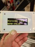
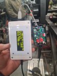
Getting back to the main thread, this being the code for the autodrive controller, i had a call from clock bloke to say when he got to his unit this morning a picaxe controlled autodrive had stopped working, i had made a small change to the code only so that he can have a plug in oled display to see its status, he can see the voltage, the fault registers and a string of numbers which are the main settings being used, so he can always see what code is in a drive, also i can reprogram the picaxe through this interface.
On this drive last week i was asked to reduce the pulse time after the last activation from 501 = approx 400ms to 250 = approx 200ms then the system failed, but not straight away, still took a few hundred activations, i need to get to the bottom of what the tilt switch does wrong from time to time, maybe 1 in 100 activations, atleast we are using a picaxe now and can alter code to help if needed.
I have been asked if i can make the tilt switch code work for a tilt switch that is "on" normally and have it look for an "off" ie the opposite to how it works now, i know hippy gave a solution for use on the tilt switch test rig which showed that the tilt switches seem to work better working backwards.
Today i have bought a turret clock so i can have a live test bed, just need to go collect it this week
Attachments
-
 121.7 KB Views: 20
 -
34.5 KB Views: 12
-
 141.4 KB Views: 20
Last edited:
Jack Burns
New Member
i had a call from clock bloke to say when he got to his unit this morning a picaxe controlled autodrive had stopped working
I assume the clock is stopping due to the autowind spring tension being lost, rather than stopping because the clock needs cleaning and lubricating?On this drive last week i was asked to reduce the pulse time after the last activation from 501 = approx 400ms to 250 = approx 200ms then the system failed, but not straight away, still took a few hundred activations, i need to get to the bottom of what the tilt switch does wrong from time to time, maybe 1 in 100 activations, atleast we are using a picaxe now and can alter code to help if needed.
As the problem is intermittent, could the problem be with the motor rather than a tilt switch. It’s possible the motor has a bad contact on one of the segments of the commutator and the motor occasionally comes to rest on that segment.
Rampz
Well-known member
Yes Jack that was they way it stopped this time, i have a reset button to reset the stall condition i ask the bloke if he tried pressing that when he came to it, he said he tried that and it didn't do anything, the motor and gearboxes used are 12v car wiper motors and the are sourced directly from the manufacturer in Italy, this is a brand new unit, the issue only showed when i was asked to reduce reduce the delay on time, its possible it would have failed anyway at this time.I assume the clock is stopping due to the autowind spring tension being lost
Just strange how it can have recorded so may stalls, considering it takes 6 seconds of continious on signal to get there then after which it needs to see atleast an off signal before an on signal.
I just asked him if the led that is paralell with the motor lit up when the reset button was pressed, he siad it didn't light either, also i have a heart beat led that shows normal operation and he says it was flashing normally, the heart beat led is really just the SEROUT voltage etc data every second that stops when in a fault condition, so makes me wonder if there is something slightly a miss in the code, a chance to get out of sync or something.
In normal operation if it had been sat in a stall position, like it had been driving for more than six seconds, it would stoped and the heartbeat led would be stopped, the bloke says the tilt switch would definately have been permantly on in the position he found the clock, completely unwound, i have noticed it take quite a few miliseconds to send the heartbeat data and i wonder if that effects it anyway?
Or can anyone see in the code a possibility for falling out of the loop, its unlikley it actually had 253 stalls?
David_Reynolds
Well-known member
Hi all, I just dived in here again , can I add my two penneth to this. From what I know about the tilt switch methodology I would like to ask if the switch is handable, since the best way to set it is in N/C is satisfied and therefore when it tilts and breaks contact, the drive operates and momentarily pulls the contacts away from the ball / glob, the drive moves until the ball catches up with it, ( that is going to be the absolute minimum requirement).Getting back to the main thread, this being the code for the autodrive controller, i had a call from clock bloke to say when he got to his unit this morning a picaxe controlled autodrive had stopped working, i had made a small change to the code only so that he can have a plug in oled display to see its status, he can see the voltage, the fault registers and a string of numbers which are the main settings being used, so he can always see what code is in a drive, also i can reprogram the picaxe through this interface.
On this drive last week i was asked to reduce the pulse time after the last activation from 501 = approx 400ms to 250 = approx 200ms then the system failed, but not straight away, still took a few hundred activations, i need to get to the bottom of what the tilt switch does wrong from time to time, maybe 1 in 100 activations, atleast we are using a picaxe now and can alter code to help if needed.
I have been asked if i can make the tilt switch code work for a tilt switch that is "on" normally and have it look for an "off" ie the opposite to how it works now, i know hippy gave a solution for use on the tilt switch test rig which showed that the tilt switches seem to work better working backwards.
Today i have bought a turret clock so i can have a live test bed, just need to go collect it this week
N/O is not good since the moment the circuit contacts, the drive moves, and follows the ball causing multiple hits, and a random reset point acording to the bounces. This could be covered by ignoring the reset position and just doing a timed response to the first hit BUT making sure that it achieves a full clearance and reset of the switch.
Could it be that your timed response to the drive does not allow the switch to reach its reset position?
Also if the pull direction is handed so to must the switch be.
Last edited:
Rampz
Well-known member
Thanks DavidThis could be covered by ignoring the reset position and just doing a timed response to the first hit BUT making sure that it achieves a full clearance and reset of the switch.
If its on the clock drum then that could work, but on the chimes drum and depending what hour it will be striking the motor may need many pulses during a several second burst.
Maybe a short delay of 400ms before the motor reacts to the first pulse.
If you look at the code you will see that multiple pulses less than the 400ms are ignored or what ever the pulse time is set to.
hippy
Ex-Staff (retired)
Can you link to the exact code you have running as I've lost track of what that is, and you say you recently changed the code, reduced the delay on time.makes me wonder if there is something slightly a miss in the code, a chance to get out of sync or something ... Or can anyone see in the code a possibility for falling out of the loop, its unlikley it actually had 253 stalls?
Rampz
Well-known member
Hello Hippy its in PDF format in post #170 above, i will see if i can add it in pe6 editor version too, sorted.Can you link to the exact code you have running as I've lost track of what that is, and you say you recently changed the code, reduced the delay on time.
In this code the delay is left at 400ms, so for the unit that has a possible issue, in Symbols where the delay is set, it was reduced from 501 to 250, the number 501 was calculated to include proccessing time to give 400ms including overhead
Attachments
-
14 KB Views: 7
Last edited:
PhilHornby
Senior Member
Is there any possibility that the Picaxe is (occasionally) resetting, when power is applied to the motor?Or can anyone see in the code a possibility for falling out of the loop, its unlikely it actually had 253 stalls?
(I had this when I 'picaxed' an under-counter fridge. I didn't even try to investigate the actual electrical origins of the problem - I fixed it in software instead).
Rampz
Well-known member
Good idea Phil, didn't think of that, i do have the capacitor 100nf directly across picaxe supply pins, as in on reverse of pcb and also have a 22uf next to the regulator on the control board.Is there any possibility that the Picaxe is (occasionally) resetting, when power is applied to the motor?
Still strange how the stall counter got so high, just what seemed one event and it went crazy, could be along those lines though, how did you sort it in software?
PhilHornby
Senior Member
If you are able, I would obviously recommend getting to the bottom of the hardware issue, (if that's what it is)....could be along those lines though, how did you sort it in software?
In my case, I knew I had no chance
 of doing that, so I just saved the 'context' of the program in EEPROM, so on reset it could get the compressor back into line with its previous state. (In a fridge application, using simple hysteresis, it otherwise had no idea if the temperature was previously climbing or falling).
That particular application was written back in 2014, before Hippy posted this: http://www.picaxeforum.co.uk/showthread.php?29548-Preserving-data-for-after-a-RESET-command. This allows a (small) amount of data to be stored in non-EEPROM, thus avoiding the problem of potentially wearing it out.
I used that approach in a later variable-power, variable fan-speed heater controller - which once again suffered from 'spurious resets'
(Those 56 bytes of battery-backed RAM on a DS1307 are always of use in situations like this - even if you don't actually use the clock part!)
Rampz
Well-known member
Phil i get one of these if i plug the screen into the pcb with power on, doing it on the development board i added a 1K resistor between C0 and the screen, it worked on development board but doesn't seem to on actual pcb. I did originally intened that the drives would be unplugged to add the screen then re-powered to read system details etc, but finding i could do it live on the development board i put all the info i wanted to display to be sent every second while a voltage measurement is being done.'spurious resets'
Like you say i need to find what can make this happen, seems somehow evens found a whole in the code, where it ended up in a loop around the stall counter
Jack Burns
New Member
'spurious resets'
Is the picaxe crashing/locking up, or is it just the display that’s not working when you connect it with the power on?Phil i get one of these if i plug the screen into the pcb with power on, doing it on the development board i added a 1K resistor between C0 and the screen, it worked on development board but doesn't seem to on actual pcb.
Just a guess, but could the problem be the order the pins make connection. You could try connecting the 2 power lines first, followed by the data line.
The screen may also need some initialisation codes to be sent to it before it will display properly, these could be added to your Memoryrecall subroutine.
Rampz
Well-known member
Jack this is something that happens a side from the stall issue above.Is the picaxe crashing/locking up, or is it just the display that’s not working when you connect it with the power on?
I use a pcb mount mini usb socket, connection should always be the same, power comes through the plug too, when the screen is plugged in the heartbeat led (heatbeat being a string of data) stops flashing, i would say the picaxe seems to get a power reset, the screen has the 18m2 backpack so it takes care of itself and when the autodrive starts sending data its ready for it.
PhilHornby
Senior Member
That change might be more significant than it looks.I had a call from clock bloke to say when he got to his unit this morning a picaxe controlled autodrive had stopped working, I had made a small change to the code only so that he can have a plug in oled display to see its status,
Rich (BB code):
IF TILT = Activated then

      SEROUT AXE134pin , N2400_16 , ( 254 , 212 ); Position the cursor at start of 4th line
      SEROUT AXE134pin , N2400_16 , ( "TILT SWITCH OPERATED" )     ; Send to AXE134
Rich (BB code):
      IF BTN = Pressed then
sertxd("Tilt switch operated",13,10)High MOTOR statement.But you have:I have a reset button to reset the stall condition I ask the bloke if he tried pressing that when he came to it, he said he tried that and it didn't do anything
Rich (BB code):
      for c5counter = 1 to 120
            pause 1000
      next c5counter
disconnectdisconnect).I think the problem is more likely to be in this area though...
I reckon the tilt switch needs debouncing (again) after the motor starts. Perhaps also add some debugging around that point, to determine if the Picaxe is resetting. (Set a flag using the 'hippy' technique I linked to above, and check for its presence at boot time. Remember to clear the flag when the motor is switched OFF).N/O is not good since the moment the circuit contacts, the drive moves, and follows the ball causing multiple hits, and a random reset point according to the bounces.
Last edited:
Rampz
Well-known member
Phil i did notice it was taking longer to send data than it did on the PE6 Editor, i guess from what your saying the timing difference is due to the differeances in baud rate?That change might be more significant than it looks.
Its the opposite, for 30 seconds i can do a download after which that input becomes the reset button from a stall condition , and it works just fine, i would have preffered not to have done it like that, but i was asked to provide the means to reset from a stall condition and i had already used all my pinsSo the reset button is only active for the first 30 seconds after boot - then it's disabled (by thedisconnect).
Yep it isn't too hard to flip the tilt switch around and position it to work in reverse, when i get my test rig built up i will try that, i want to be able to test it live on a clock.I think the problem is more likely to be in this area though...
I reckon the tilt switch needs debouncing (again) after the motor starts. Perhaps also add some debugging around that point, to determine if the Picaxe is resetting. (Set a flag using the 'hippy' technique I linked to above, and check for its presence at boot time. Remember to clear the flag when the motor is switched OFF).
Adding flags etc i'm not sure how to do that, it has been spoken about before in other things i have tried for fault finding, not something i have got my head around yet such that i can work out just how to code it and just where to do that etc
I need to be careful, if its a autodrive on the clock mech then it would be fine, if its on the chimes side then there will be a string of several tilt switch activations as multiple drives of the motor is required because it can be striking upto 12 times for the hour etcI reckon the tilt switch needs debouncing (again) after the motor starts
PhilHornby
Senior Member
Ah - I hadn't spotted the ...It's the opposite, for 30 seconds I can do a download after which that input becomes the reset button from a stall condition and it works just fine
Rich (BB code):
do : loop while TILT = Activated and StallReset = released '// Wait for switch to be released, btn2 = released resets motorstalled condition What does it do, if you press it immediately after boot, before the
disconnect 
Since it doesn't appear to do anything when pressed 'after a stall', can we assume that the condition resets itself, by virtue of the
low MOTOR statement that precedes it (i.e. the clock unwinds itself again and moves the Tilt switch).A very simple version, which just detects the condition, would be:Adding flags etc I'm not sure how to do that, it has been spoken about before in other things
Rich (BB code):
#Picaxe 08M2
;
; Put the Symbol, with the existing ones.
;
Symbol BORCON = $56                                   ;$116

;
; Existing code
;
INIT: ' initialisation code
      PAUSE 500
      SEROUT AXE134pin , N2400_16 , ( 254 , 1 )
;+
; NEW CODE: Check for unexpected RESET
;
      PeekSfr BORCON, b0                              ;get the BORCON register contents
      If bit6 = 0 Then
            SerTxd( "NORMAL Power-On", CR, LF )
      else
            SerTxd( "UNEXPECTED RESET", CR, LF )      ;BORFS=1
            ;
            ; Might want to do something else here.
            ;
      End If
;
;     Set flag to allow for RESET detection
;
      PokeSfr BORCON, %11000001                      ;set BORFS bit in BORCON register
;
; END OF NEW CODE.
;-We're back to the suitability of that tilt switch, for this application...I need to be careful, if it's an autodrive on the clock mech then it would be fine, if it's on the chimes side then there will be a string of several tilt switch activations as multiple drives of the motor is required because it can be striking up to 12 times for the hour etc
Perhaps the logic should be:
- On detecting TILT, send a 400mS pulse to the motor (using simple
Pulsout) - Wait say 250mS.
- If TILT is still activated, goto 1
Step 2 is less 'debounce' and more 'allow for switch to settle'.
Rampz
Well-known member
Phil its not intending to be used directly after a boot, maybe gets ready for a download that's not coming, i haven't tried it.What does it do, if you press it immediately after boot, before thedisconnect
If the tilt switch is still closed and the motor hasn't moved for some reason it will stay in the stalled condition either till the tilt switch goes open which is unlikely to happen if the motor isn't moving, so something was needed to do the same as the tilt switch going open, and when the motor is sat in the stall condition, pressing the button gives it upto 6 seconds more power to drive, it works well.Since it doesn't appear to do anything when pressed 'after a stall', can we assume that the condition resets itself,
After a stall, eg when everything goes back to normal running the button doesn't do anything useful, i think its only monitored from the stall section
Got to be a bit careful that pulses of the tilt switch aren't missed 250ms might be long enough to miss something, thats why everything is in a fast loop to make sure the tilt switch is monitored as often as possible, just a shame the tilt switch is a bit unreliable from a repeatability point of view, the clock bloke isn't current interested in changing to a different meens of detection.Perhaps the logic should be:
- On detecting TILT, send a 400mS pulse to the motor (using simple
Pulsout)- Wait say 250mS.
- If TILT is still activated, goto 1
I will have a clock at home tomorrow so i can start to see if i can make it go wrong etc
Jack Burns
New Member
When you originally started this thread, you experienced problems with button pushes being missed due to rapid presses (button represented the tilt switch).Got to be a bit careful that pulses of the tilt switch aren't missed 250ms might be long enough to miss something, thats why everything is in a fast loop to make sure the tilt switch is monitored as often as possible
However we now know a lot more about your project and it is our understanding that if the autodrive motor needs to be operated then the tilt switch will be permanently on, so it shouldn’t matter if the tilt switch was monitored less frequently as it would still be detected. Obviously you don’t want excessively long delays as you want to keep the spring tension reasonably constant.if the button is pressed many times quickly then there are presses where the LED is off for a split second
Rampz
Well-known member
Jack yep I guess so, the original need came from how the 555 was being used, kind of missing pulse detector, that was the setup for the drive on the Chimes mech whereas the clock mech was using a 555 in monostable mode, it was found that the Chimes one was suitable for both drives.However we now know a lot more about your project and it is our understanding that if the autodrive motor needs to be operated then the tilt switch will be permanently on, so it shouldn’t matter if the tilt switch was monitored less frequently as it would still be detected. Obviously you don’t want excessively long delays as you want to keep the spring tension reasonably constant.
I guess it works just as I want it to but maybe it can be made better if I can work out exactly what's required that's any different from what I thought, currently it does work really well appart from one issue that's so far only happened once.
Last edited:
PhilHornby
Senior Member
Intended or notPhil it's not intending to be used directly after a boot, maybe gets ready for a download that's not coming, I haven't tried it.
, if you press it, the Picaxe resets about 2 seconds after releasing it. (I tested it).Have you encountered a 'stall' in the wild, that required the Reset button pressingIf the tilt switch is still closed and the motor hasn't moved for some reason it will stay in the stalled condition either till the tilt switch goes open which is unlikely to happen if the motor isn't moving, so something was needed to do the same as the tilt switch going open, and when the motor is sat in the stall condition, pressing the button gives it upto 6 seconds more power to drive, it works well.
(You previously said you had a Stall count of 253 and the Reset button had no effect. Surely it can't have 253 genuine detects of Tilt after 6 seconds, none of which resulted in the program locking-up in the 'Stall Reset loop')
I can see that you want to respond to the first sign of a 'Tilt'. When the proposed pulsout completes, you know exactly where the winding mechanism ought to be.Got to be a bit careful that pulses of the tilt switch aren't missed 250ms might be long enough to miss something
I chose 250mS (for a potential second 'crank'), because it seemed a good compromise between the Tilt Switch being properly 'settled' and the Clock becoming terminally unwound.
Select-On-Test though
Rampz
Well-known member
Thanks Phil, in the autodrive that push button is accessed with a paper clip through a hole in the motor control box, I guess the reset is not from code but rather from pulling that pin highIntended or not
Yep I wanted to catch the first sign of the tilt switch being operated, they want to keep the angle that is required quite small and we know the switch doesn't close very cleanly there can be several bounces, 7 bounces is the most I found on the test rig, but I wasn't happy about the test method I was usingI can see that you want to respond to the first sign of a 'Tilt'. When the proposed pulsout completes, you know exactly where the winding mechanism ought to be.
Rampz
Well-known member
I don't think it can of had that many stalls considering but something caused the counter to increment and for the motor to be sat in the unwound position where the tilt switch would have been fully closed, I wasn't there to witness how he found the clock. The picture of the screen he sent to me when he plugged it in to try and see the problem.(You previously said you had a Stall count of 253 and the Reset button had no effect. Surely it can't have 253 genuine detects of Tilt after 6 seconds, none of which resulted in the program locking-up in the 'Stall Reset loop')
And No so far I have never had a stall that needed a reset to be pushed in the wild, although the clock bloke simulated a few and the reset worked just fine
PhilHornby
Senior Member
A thought ...
It seems the initial tilt can be detected reliably - but after that, the tilt sensor issues a fairly meaningless set of signals, until it has stopped moving and settled - all bets are off, until that point.
For the Powertrain, a single, calibrated crank by means of a timed pulse to the motor, will probably wind the clock by the same, correct amount every time. The remaining issue is therefore for the striking mechanism(s), which has more variable requirements.
The addition of a DS3231 clock module could overcome that...
I'm envisaging something along the lines of: Pulsing the motor, a set number of times, for a pre-set period, for each initial Tilt detection - based on pre-set parameters. So for example, at 11am, it knows that 6 'cranks' are required ... and at 1pm, only one; that sort of thing. Same sort of idea for the ¼,½ & ¾ hours. The length of the Pulse, time between Pulses and number of Pulses can be different in each case; there are not that many of them to store.
It may even be possible for it to learn those parameters, when initially installed - if the clock can be made to strike each hour in turn; which I reckon it can.
Or something along those lines
Rampz
Well-known member
Phil really interesting idea, things i need to consider just how to calibrate it, the autodrive would need to be self installed on the clock correctly before a calibration routine can begin, what feedback can be given to the user that its progressing correctly, ideally it would all want to be self contained.I'm envisaging something along the lines of: Pulsing the motor, a set number of times, for a pre-set period, for each initial Tilt detection - based on pre-set parameters. So for example, at 11am, it knows that 6 'cranks' are required ... and at 1pm, only one; that sort of thing. Same sort of idea for the ¼,½ & ¾ hours. The length of the Pulse, time between Pulses and number of Pulses can be different in each case; there are not that many of them to store.
Then there is the year on year error in time to allow for, maybe once a month it needs to compare the actual time against the starting of striking 1 oclock and compater to 30 days pervious and make any adjustment needed to stay in the same area, this could be done 6 monthly, something would be needed.
I would be really interested to see what could happen going down this route, could ideally use a tiny screen for set up, its going to be a challenge adding a battery backed clock module to an already full box, i guess a deeper box could be used to help out
The clock module would need to auto change over to Daylight Saving Time, although all it would need to do is read the settings 1 hour forward or 11 hours back, since the clock would need its time altering anyway maybe best have a mech that the user can press etc when the change is made, because it could be several hours before the user alters the clock time.
Edit
Thinking further maybe need an 8x2 screen on top of control box with 1 push button that would only be active during say 30 seconds after power up to allow the screen to be incremented forward until the next chime to happen is correct with clock time, then maybe for summer winter change over the user will need to alter clock anyway so they can also increment the display to show the next expected chime type etc?
Last edited:
Jack Burns
New Member
The existing code increments the Stall count only once after 6 seconds, however if the Tilt switch is permanently on and the Reset button has been pushed, then the Stall count will increment again. This can be repeated during a stall but does need the reset button to be pressed each time. So lots of Reset button pushes required to get to 253.Surely it can't have 253 genuine detects of Tilt after 6 seconds
Make me wonder if electrical noise is getting to the Serial In pin (used for Reset button) and flagging a stall reset without the button being pushed.
The electrical noise may only happen at spurious times, so maybe the church roof alarm, nearby mobile phone/phone masts, or lack of capacitors around the voltage regulator.
PhilHornby
Senior Member
Um - that's a possibility. I've suffered something similar - the cause being the start up of Central Heating pump (hardly a massive electrical load - but nonetheless...). Again, I addressed that problem in software - I just made it require a slightly longer pressMake me wonder if electrical noise is getting to the Serial In pin (used for Reset button) and flagging a stall reset without the button being pushed.
PhilHornby
Senior Member
Having slept on it, maybe it's not as complicated as it sounds...things I need to consider just how to calibrate it, the autodrive would need to be self installed on the clock correctly before a calibration routine can begin, what feedback can be given to the user that its progressing correctly, ideally it would all want to be self contained.
... snip ...
The clock module would need to auto change over to Daylight Saving Time,
I don't think it actually needs a DS3231 in order to know the time - it would just need synchronising with real-time once. After all, 2pm always follows 1pm, half-past always follows quarter-past etc
- it would just need to know where it was in the 'sequence'.Maybe the calibration wouldn't be as bad as it sounds either. It's something you can investigate when you get your own clock.
Perhaps you'll find, that the values are multiples of one another. (For example, when you know what is needed to rewind after striking 1pm, perhaps the values required for winding after all later strikes will all be predictable, i.e. in some fixed ratio or pattern)
Last edited:
Rampz
Well-known member
Jack seems likely the only way it could have got in to such a mess, the screen wasn't attached when it went stupid, so the length of track connected to the picaxe pin would have been very short, maybe 30-40mm, any ideas on possible damping this pin?Make me wonder if electrical noise is getting to the Serial In pin (used for Reset button) and flagging a stall reset without the button being pushed.
The clock was on test in the middle of the clock bloke's workshop so really well away from any interference, but something happened.
After the regulator it has a 22uf capacitor within 10mm, and there is a 100pf capacitor connected directly to the supply pins of the picaxe, the capacitor is on the reverse of the pcb.
The power source is a smart lead acid battery charger across a 10ah 12v lead acid maintenace free battery, during some phases of float charging i guess its possible there could be some noise, i imagine the dc derived from the charger is not a true dc and more likely i high frequency type of dc, maybe a large capacitor where power is connected to the motor pcb?
Also maybe some debounce on the stall-reset switch to rule out interference?
Yep i did start thinking along those lines, it would be good for the control unit to be able to display somehow where it thinks it is in the cycle, it could then be incremented to the right place after a form of calibration and if the time gets changed for DST then it can be incremented to the right place after altering the church clock.I didn't think it actually needs a DS3231 in order to know the time - it would just need synchronising with real-time once. After all, 2pm always follows 1pm, half-past always follows quarter-past etc
These things are self install i'm going to factor in stupidity etcMaybe the calibration wouldn't be as bad as it sounds either. It's something you can investigate when you get your own clock.
Yes quite possible, currently my test clock only has a clock drive because the clock bloke wants me to work on the grab mech at the momentPerhaps you'll find, that the values are multiples of one another. (For example, when you know what is needed to rewind after striking 1pm, perhaps the values required for winding after all later strikes will all be predictable, i.e. in some fixed ratio or pattern)
Jack Burns
New Member
Did you really mean 100pF as Rev-Ed recommend 100nF as close to the picaxe as possible?After the regulator it has a 22uf capacitor within 10mm, and there is a 100pf capacitor connected directly to the supply pins of the picaxe, the capacitor is on the reverse of the pcb.
The LP2950CZ datasheet also recommends a capacitor on its input - do you have one fitted?
"A bypass capacitor is recommended across the LP2950/LP2951 input to ground if more than 4 inches of wire connects the input to either a battery or power supply filter capacitor."
The pause 500 in your initialisation is actually pausing for 125ms as your running your code at 16MHz. I suggest increasing this to "pause 4000" which will give you 1000ms at 16MHz. I find my 16x2 OLD need this long to reliably initialise.
Code:
init: ' initialisation code
  pause 500
SEROUT AXE134pin , N2400_16 , ( 254 , 1 )
Are you using the standard firmware on the OLED backpack, or do you have a customised startup message? as it's possible that any new message written by the autowind unit could be mis-interpreted if the OLED wasn't starting with a clear screen?
I notice you can get the code into a state where you think it's working but it's actually doing something else, so the motor can't be driven. Your RECALL button flashes the heartbeat LED on C.0 at a rate of 1.25 secs on and 1.25 secs off (allowing the faults to be counted), so the flashing heartbeat LED can give the impression all is well, however this will take over 10.5 minutes to complete if you did have a genuine fault count of 253, and during this time the motor will never be driven.
For the time being, I would be inclined to disable the RECALL button (or modify the memoryrecall subroutine) to avoid the possibility of getting the code stuck in a potentially long fault recall sequence.
I'm not sure if this is exactly what you had in mind, but I thought that if the button had to be held down for a set period of time, then it would be very unlikely to get an accidental reset from interference.Also maybe some debounce on the stall-reset switch to rule out interference?
The following code requires the StallReset button to held down for 2 seconds continuously for the reset to take place. The actual delay is not really that important as the autodrive has already stalled, however it can be easily changed if you want a different delay.
Rich (BB code):
    ' *** Original line rem'd out ***
    'do : loop while TILT = Activated and StallReset = released '// Wait for TILT switch to be released OR StallReset to be pushed

    ' *** New code to replace original line ***
    '// Wait for TILT switch to be released OR StallReset pushed for 2 secs
    Time = 0
    do
    if StallReset <> Pressed then
      Time = 0
    end if
loop while TILT = Activated and Time < 2Jack Burns
New Member
Just found an interesting document...
The Evolution Of Tower Clock Movements And Their Design Over The Past 1000 Years
and lots of other interesting stuff on their main website...
MAGNIFICENT TIME MACHINES
Preservation, restoration and collecting of specialized timepiece
http://www.my-time-machines.net/
The Evolution Of Tower Clock Movements And Their Design Over The Past 1000 Years
and lots of other interesting stuff on their main website...
MAGNIFICENT TIME MACHINES
Preservation, restoration and collecting of specialized timepiece
http://www.my-time-machines.net/
Rampz
Well-known member
Jack yes sorry its 100nf my mistake.Did you really mean 100pF as Rev-Ed recommend 100nF as close to the picaxe as possible?
No i don't have one at this point i will look into what it recommendsThe LP2950CZ datasheet also recommends a capacitor on its input - do you have one fitted?
Yep good point, the main reason for that being there was after a download when there is loads of weird stuff showing on the screen from the download it clears the screen at this point the screen has been powered for some time, but i can increase itThe pause 500 in your initialisation is actually pausing for 125ms as your running your code at 16MHz. I suggest increasing this to "pause 4000" which will give you 1000ms at 16MHz. I find my 16x2 OLD need this long to reliably initialise.
I don't have a start up message, after a screen clear it gets the voltage details, and fault registersAre you using the standard firmware on the OLED backpack, or do you have a customised startup message? as it's possible that any new message written by the autowind unit could be mis-interpreted if the OLED wasn't starting with a clear screen?
On the drives the recall button is covered its not intended to be used by the userFor the time being, I would be inclined to disable the RECALL button (or modify the memoryrecall subroutine) to avoid the possibility of getting the code stuck in a potentially long fault recall sequence.
I assume by that you mean because the recall button had been pressed and the heartbeat was actually the memory being recalled?I notice you can get the code into a state where you think it's working but it's actually doing something else,
I have been thinking loads about the problem and why so many stalls, i have just spoke to the clock bloke to see just how he found the drive and just what he did, the stall-reset button is recessed since its a smd switch, he has fitted a slim plastic tube behind the lid to guide users to press the button if required, when the drive went wrong the lid was fitted, i think the tube was therefore pushing the stall-reset permantly would only cause an issue if the unit went into stall.
Ok he asked me to reduce the drive pulse to 200ms which i did, now this drive is on the chimes side of the clock, when its triggered it can drive continiously for between 1 and 12 chimes, i think what was happening manly for the higher hours that the 200ms wasn't long enough for the tilt switch to open so the picaxe would see the motor running continously and the tilt switch permantly on so it would go into stall, stall-reset is pushed permantly, so stall resets and counter increments, and this just keeps repeating as required, this doen't yet explain why the drive stopped alltogether.
But what is the effect on the drive if its sat in its stall position with tilt switch showing closed and the picaxe restarts. So picaxe restarts with tilt switch closed, it would show normal operation i think with heart beat, stall-reset wouldn't work because it wouldn't think its in a stall, motor won't drive either because it will never see the tilt go closed because it was already closed??
Maybe then tilt-reset maybe need to be able to give a drive pulse if used when not in a stall?
Maybe need to look at ways for picaxe to start and think that a closed tilt switch is a reason to give a pulse?
I think that's worth looking at using regardless JackThe following code requires the StallReset button to held down for 2 seconds continuously for the reset to take place. The actual delay is not really that important as the autodrive has already stalled, however it can be easily changed if you want a different delay.
Edit
Just being try to see what happens when the drive is put into stall when tilt is closed then restart the picaxe by power cycling, first try seems to work just.
Second test,
Got drive to point where tilt switch closed and it went into stall, I had stall-reset already permanently pressed, stall constantly reset, counter incrementing constantly, cycled power, at this point the heart beat was actually the picaxe constantly trying to do a download at this point nothing worked, released stall-reset button, picaxe started normally and motor drove back to normal position.
Most likely code is just fine, need to be careful with pulse time, and clock bloke needs to be careful around stall-reset button.
If picaxe restarts for some reason it still works fine so that's not an issue as long as stall-reset isn't pushed at the time.
When the clock bloke got to the drive he removed the cover and plugged screen in, the picaxe will have restarted, the screen was given the normal info but the drive didn't work even though the tilt switch was closed so still something strange was going on, but I can explain most of it.
Last edited: