EDIT: Thinking further, the addition of the RS-232-C to TTL converter might have a bearing - and might make it easier to multiplex the inputs together, at that point.
I don't see any issues at the Masters end, as each Master will have its own RS232 max3232, but at the slave display end not sure if the 3x RS232's will be connected together before the convertor (max3232) then after the convertor its just tx and rx, of if i have 3x max3232 with the TTL side linked together?
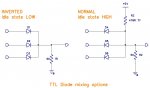
Will there be pullup resistors used on the TX and RX connections TTL side to the RS232 converter, and how to go about mixing signals with diodes?
With using a multicode cable between master and slave i will be able to have both TX and RX so i expect the Slaves can send a command to each Master asking for data to avoid problems?
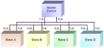
Hippy did think originally there would be 3x masters talking to 1x display slave, but seems with RS232 it will now be the opposite with a display Master talking to 3x Slaves?
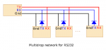
Maybe someone has a sketch of the connections for all this, getting rather confusing at the moment, Found this sketch, see mention of diodes and resistors etc
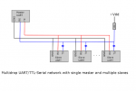
Attached the 3rd image is multidrop TTL
Edit
Found this:
The RS-232 driver (Maxim Part No. MAX242) can be
tri-stated under software control. This allows standard point-to-point full duplex communications, as well as a multi-drop configuration with one
master (a single QVGA Controller or a desktop computer) and multiple QVGA Controller
slaves. To implement this multi-drop scheme, each slave keeps its RS-232 transmitter
silent until it is addressed by the master and is given permission to transmit. The advantage of such a multi-drop RS-232 network is that the communications are
full duplex, with each communicating party capable of simultaneous transmission and reception of data. The software routines, RS232Transmit() and RS232Silent() control the dual RS232 transmitters on the board.
")
 as well, to bring the villagers running