Hippy I would like to adapt, if possible, the concept expressed in your post “Very accurate 18X Timing” 12/06/07, however the link is currently inaccessible. Do you still have that code archived somewhere?
Its not so much the accuracy I’m after, as the method, although accuracy will be a bonus.
In the August 08 Silicon Chip, a reader requested a device to balance pendulum clocks. The Editor misunderstood his request to be a rate calibrator and was of little help. I may be able to help out here but I want to do a feasability first.
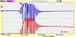
As background, a pendulum must swing equally in both directions with respect to the escape mechanism. If tilted to one side it will overrun the escape lever in one direction and underrun in the other. This will eventually cause the pendulum to lose power and stop. The escape mechanism actually adds power to the pendulum via the clock spring or weight to overcome losses due to air drag etc.
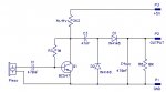
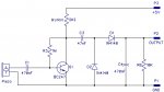
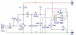
Over 12 years ago I built such a device for a colleague of mine who restored tower clocks. It consisted of a piezo pickup, an amplifier, some logic, 2 counter/LCD drivers and 2 LCDs. It also used an LM386 and speaker to listen to the movement. The counter/drivers were quite expensive 7224 devices.
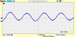
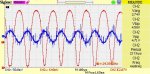
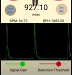
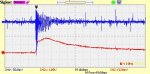
My original design simply displayed the period of the left and right swing. The piezo listened to the escape ticks just like an automotive knock sensor. If the clock is unbalanced then the tick periods will be different due to pendulum overrun.
These days I believe it could easily be done with the same analog front end, picaxe and 2x16 LCD.
I thought it might be fun to revisit an old project using current technology. I am planning to use the analog derived monostable pulse to interrupt and then read the count value of the 32 kHz input.
A picaxe design could show both periods on the bottom line. The top line could display a rolling character to simulate the pendulum position. Optionally, the differential time could be displayed by a mode select switch.
The way I see it, the counting has to be real time, back to back for each swing. There is no time for display code unless counting is in the background. With background counting, the only lost real time will be the interrupt routine. This will stop the count and copy it to a word variable, then reset and start the counter. I think your earlier post could be the critical core of the required code. As I haven’t seen your code, is this possible?
Even with a really short pendulum such as a mantle clock, I should have at least 300ms to do houskeeping, check battery, display data and messages before the next interrupt. Big Ben would give me several seconds to play with. This gives an idea of the count range. They can be arbitrary units unless I want to calibrate rate as well.
Rate accuracy will be limited by crystal drift and the interrupt routine execution time. But might be useful for initial setting of pendulum length.
Happy to hear any thoughts or ideas from anyone.
Cheers
Alan
Its not so much the accuracy I’m after, as the method, although accuracy will be a bonus.
In the August 08 Silicon Chip, a reader requested a device to balance pendulum clocks. The Editor misunderstood his request to be a rate calibrator and was of little help. I may be able to help out here but I want to do a feasability first.
As background, a pendulum must swing equally in both directions with respect to the escape mechanism. If tilted to one side it will overrun the escape lever in one direction and underrun in the other. This will eventually cause the pendulum to lose power and stop. The escape mechanism actually adds power to the pendulum via the clock spring or weight to overcome losses due to air drag etc.
Over 12 years ago I built such a device for a colleague of mine who restored tower clocks. It consisted of a piezo pickup, an amplifier, some logic, 2 counter/LCD drivers and 2 LCDs. It also used an LM386 and speaker to listen to the movement. The counter/drivers were quite expensive 7224 devices.
My original design simply displayed the period of the left and right swing. The piezo listened to the escape ticks just like an automotive knock sensor. If the clock is unbalanced then the tick periods will be different due to pendulum overrun.
These days I believe it could easily be done with the same analog front end, picaxe and 2x16 LCD.
I thought it might be fun to revisit an old project using current technology. I am planning to use the analog derived monostable pulse to interrupt and then read the count value of the 32 kHz input.
A picaxe design could show both periods on the bottom line. The top line could display a rolling character to simulate the pendulum position. Optionally, the differential time could be displayed by a mode select switch.
The way I see it, the counting has to be real time, back to back for each swing. There is no time for display code unless counting is in the background. With background counting, the only lost real time will be the interrupt routine. This will stop the count and copy it to a word variable, then reset and start the counter. I think your earlier post could be the critical core of the required code. As I haven’t seen your code, is this possible?
Even with a really short pendulum such as a mantle clock, I should have at least 300ms to do houskeeping, check battery, display data and messages before the next interrupt. Big Ben would give me several seconds to play with. This gives an idea of the count range. They can be arbitrary units unless I want to calibrate rate as well.
Rate accuracy will be limited by crystal drift and the interrupt routine execution time. But might be useful for initial setting of pendulum length.
Happy to hear any thoughts or ideas from anyone.
Cheers
Alan