inglewoodpete
Senior Member
Background
About a year ago, my wife and I bought a camper-trailer. It was fitted with a 10W LED light strip in the main tent which is great when you want a bright light. The light switch was mounted on a side pole at the foot of the bed: not the best location when you're in bed. When turned on in the middle of the night, it was pretty bright and bound to wake the sleeping partner!
We decided that a dimmer was called for, controlled from the head of the bed but switchable from the foot of the bed when stepping into the tent at night.
The solution
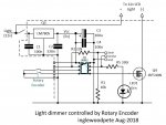
I decided on a small diecast enclosure, with master switch, mounted in the original switch position at the foot of the bed near the tent's doorway. An 08M2 PICAXE would drive an N-channel MOSFET with PWM to control the light intensity. A rotary encoder, mounted at the centre of the head of the bed, would control the dimming. The master switch would provide power to the PICAXE, which starts the PWM at 100% at bootup. The camper has a 12v 200Ah battery bank, so when the encoder turns the light down to 0% (off), the standby current to the PICAXE is insignificant.
Algorythm
One problem when using a PICAXE to read two input pins before making decisions on encoder movement and direction is the amount of time for individual commands to be executed. The microcontroller needs to read the inputs, compare the encoder position value with the previous one and make decisions on the result. If the PIC should miss a 2-bit position code, this upsets the sequence, and consequently the direction of the encoder cannot be determined. By reading the entire port, then masking out any unwanted bits, the instantaneous encoder position can be read reliably. Of course, running the PICAXE at its maximum speed helps the cause, too.
So, in a nutshell, the 08M2 reads and saves the two encoder bits and places them alongside the two previously recorded bits. All stored in one half of a byte variable (nibble). For added integrity checking, the previous nibble is then held in the other nibble. This way, the byte can be compared with a known (constant) value to determine the direction that the encoder shaft has been turned.
Development
Code was developed on an AXE092 Schools Experimenter development board with an 08M2. Initially, I tried to use the encoder without a knob on the shaft. This resulted in the two-bit codes changing too quickly for the PICAXE to track reliably. Things became much more reliable after I fitted a 23mm knob: far more realistic than the bare shaft, anyway.
For those of you who want to replicate these experiments, you can breadboard the circuit following the I/O pin allocations described in the code. The rotary encoder was a cheap one I bought from Altronics but there are many suitable types available. Basically, the encoder has three pins: the centre one was common to both phase switches and the outer two were the switched phases. I used the PICAXE's internal weak pullup resistors via the PullUp command, with the encoder's phase switches pulling the two encoded lines low as its shaft is rotated.
I have broken the development of the software into three stages, with three progressive working pieces of code. Due to forum posting limitations, I have posted these programs progressively, below.
About a year ago, my wife and I bought a camper-trailer. It was fitted with a 10W LED light strip in the main tent which is great when you want a bright light. The light switch was mounted on a side pole at the foot of the bed: not the best location when you're in bed. When turned on in the middle of the night, it was pretty bright and bound to wake the sleeping partner!
We decided that a dimmer was called for, controlled from the head of the bed but switchable from the foot of the bed when stepping into the tent at night.
The solution
I decided on a small diecast enclosure, with master switch, mounted in the original switch position at the foot of the bed near the tent's doorway. An 08M2 PICAXE would drive an N-channel MOSFET with PWM to control the light intensity. A rotary encoder, mounted at the centre of the head of the bed, would control the dimming. The master switch would provide power to the PICAXE, which starts the PWM at 100% at bootup. The camper has a 12v 200Ah battery bank, so when the encoder turns the light down to 0% (off), the standby current to the PICAXE is insignificant.
Algorythm
One problem when using a PICAXE to read two input pins before making decisions on encoder movement and direction is the amount of time for individual commands to be executed. The microcontroller needs to read the inputs, compare the encoder position value with the previous one and make decisions on the result. If the PIC should miss a 2-bit position code, this upsets the sequence, and consequently the direction of the encoder cannot be determined. By reading the entire port, then masking out any unwanted bits, the instantaneous encoder position can be read reliably. Of course, running the PICAXE at its maximum speed helps the cause, too.
So, in a nutshell, the 08M2 reads and saves the two encoder bits and places them alongside the two previously recorded bits. All stored in one half of a byte variable (nibble). For added integrity checking, the previous nibble is then held in the other nibble. This way, the byte can be compared with a known (constant) value to determine the direction that the encoder shaft has been turned.
Development
Code was developed on an AXE092 Schools Experimenter development board with an 08M2. Initially, I tried to use the encoder without a knob on the shaft. This resulted in the two-bit codes changing too quickly for the PICAXE to track reliably. Things became much more reliable after I fitted a 23mm knob: far more realistic than the bare shaft, anyway.
For those of you who want to replicate these experiments, you can breadboard the circuit following the I/O pin allocations described in the code. The rotary encoder was a cheap one I bought from Altronics but there are many suitable types available. Basically, the encoder has three pins: the centre one was common to both phase switches and the outer two were the switched phases. I used the PICAXE's internal weak pullup resistors via the PullUp command, with the encoder's phase switches pulling the two encoded lines low as its shaft is rotated.
I have broken the development of the software into three stages, with three progressive working pieces of code. Due to forum posting limitations, I have posted these programs progressively, below.

")