Hairy Animal
Member
I have a simple circuit monitoring four magnets on a pulley wheel to measure the speed and direction of the shaft it's attached to.
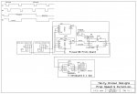
The circuit diagram above shows how it works, the two Hall Effect sensors being mounted close together so that as a magnet passes them, it activates first one and then the other with a bit of overlap which allows the direction to be established. The whole thing seems to work very well in my tests so far.
Using the PULSEIN command to measure the high period of the pulse train seems to be ideal. It times out after 0.65536 s which equates to a shaft speed of about 23 rpm below which I'm not too worried about how fast it's going. At the other end of the scale I can measure rates up to 999 rpm with sufficient accuracy which should also be fine. That side of it I've tested and everything looks very good. The output from the calculations is sent to a remote receiver via a simple 433 MHz link as eight characters which define where the transmission has come from as well as the speed and direction of the shaft.
Data from other devices is also sent to the same remote receiver, so when the shaft is stationary, I don't want to clog up the airwaves with lots of repeated zero data, but once it's moving I do want regular updates.
So I thought I'd try using the interrupt facility (which is new to me in PicAxe) in order to exit a ten second delay between repeated transmissions of the stationary message:
It does sort of work but has a major problem because when the pulses slow down and stop, the 4013 output can be left in either a high or low state. Clearly, if it's in the high state, it will keep triggering the interrupt, so what I'd ideally like is an edge triggered interrupt which looks only for a +ve going edge. This doesn't appear to be possible on an 8M2 though.
I'd be grateful for any thoughts please on a work-around for this to escape from the ten second (or longer) delay?
Thanks.
The circuit diagram above shows how it works, the two Hall Effect sensors being mounted close together so that as a magnet passes them, it activates first one and then the other with a bit of overlap which allows the direction to be established. The whole thing seems to work very well in my tests so far.
Using the PULSEIN command to measure the high period of the pulse train seems to be ideal. It times out after 0.65536 s which equates to a shaft speed of about 23 rpm below which I'm not too worried about how fast it's going. At the other end of the scale I can measure rates up to 999 rpm with sufficient accuracy which should also be fine. That side of it I've tested and everything looks very good. The output from the calculations is sent to a remote receiver via a simple 433 MHz link as eight characters which define where the transmission has come from as well as the speed and direction of the shaft.
Data from other devices is also sent to the same remote receiver, so when the shaft is stationary, I don't want to clog up the airwaves with lots of repeated zero data, but once it's moving I do want regular updates.
So I thought I'd try using the interrupt facility (which is new to me in PicAxe) in order to exit a ten second delay between repeated transmissions of the stationary message:
Code:
Main:
;
SETINT %00010000, %00010000
;
PULSIN Count_in , 1 , puls_ln ; Measure the positive part of the square
					; wave which represents 1/4 of a revolution.
IF puls_ln = 0 THEN
	SEROUT TxData_out, N2400, ("PS  0rpm")
	PAUSE 10000 		; Only output the stopped data every ten secs.
					; An interrupt will break out of this pause.
	GOTO main   		; A zero value implies the rate is too slow
					; to measure, i.e. less than about 23 rpm
					; or stationary.
ENDIF
;
SETINT OFF  			;
;	Rest of the program here
;
;
interrupt:
					; Come here when the shaft is rotating.
PAUSE 650   			; Wait until the PULSIN measurement is complete.
;
SETINT %00010000, %00010000
;
RETURNI'd be grateful for any thoughts please on a work-around for this to escape from the ten second (or longer) delay?
Thanks.
")