fernando_g
Senior Member
I'm building an emulator for an AC powerline reed frequency meter.
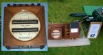
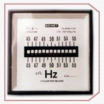
If you have not seen such a meter, please see the attached photo.
Essentially, an powerline electromagnet excites a line of reeds, which have slightly different resonant frequencies. The reed whose resonant frequency is closest to the the actual AC frequency, will have a very wide amplitude, whereas the immediate reeds will show a smaller amplitude, and the rest of the reeds are quiet, as shown in the image.
I've the software all fleshed out and operational, but my question to you, the best and brightest, is how to actually simulate the reed display.
I attempted with a 16 column LCD but the results were...naaah. Not aesthetically pleasing.
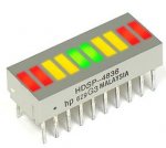
My next though will be with LEDs, there are many nice looking LED bargraphs cheaply available.
To show the resonant frequency, I would fully light up the corresponding LED, and dim the two adjacent LEDs, via PWM.
And there lies my puzzle...how to achieve that?
I originally used three external 4 to 16 (CD4514) decoders . One of them drives the LED at full brightness, the other two thru PWM, drive the dimmed ones.
But the solution is very kludgy and enormous...I don't like it at all. Not at all.
???????????
If you have not seen such a meter, please see the attached photo.
Essentially, an powerline electromagnet excites a line of reeds, which have slightly different resonant frequencies. The reed whose resonant frequency is closest to the the actual AC frequency, will have a very wide amplitude, whereas the immediate reeds will show a smaller amplitude, and the rest of the reeds are quiet, as shown in the image.
I've the software all fleshed out and operational, but my question to you, the best and brightest, is how to actually simulate the reed display.
I attempted with a 16 column LCD but the results were...naaah. Not aesthetically pleasing.
My next though will be with LEDs, there are many nice looking LED bargraphs cheaply available.
To show the resonant frequency, I would fully light up the corresponding LED, and dim the two adjacent LEDs, via PWM.
And there lies my puzzle...how to achieve that?
I originally used three external 4 to 16 (CD4514) decoders . One of them drives the LED at full brightness, the other two thru PWM, drive the dimmed ones.
But the solution is very kludgy and enormous...I don't like it at all. Not at all.
???????????
Attachments
-
 12.6 KB Views: 42
 -
 4.9 KB Views: 36
") ), how about bleeding "dim" currents to all the LEDs (or perhaps even using the internal weak pullup resistors, if the LEDs are reasonably efficient) and then the associated PICaxe pins "brighten" the central LED and "short out" all the LEDs that are required to be off.
), how about bleeding "dim" currents to all the LEDs (or perhaps even using the internal weak pullup resistors, if the LEDs are reasonably efficient) and then the associated PICaxe pins "brighten" the central LED and "short out" all the LEDs that are required to be off.