der_fisherman
Member
Hi everyone here on the PICAXEForum, I want to write a letter of my experiences in the 1 st month or so with PICAXE. Also, I want to thank everyone here, both those that have already helped me and those who have not (as yet!).")
I am using a PICAXE 28X1 chip in a 28 Pin project Board by the way.
As I have a background in computers, though the first one was in the 1960’s, but was only an onboard missile guidance system for RN Destroyers, about as big as a small house!!! I did imagine that after my almost 40 years work as a technical specialist and my programming knowledge, that I would find PICAXE easy. How wrong I was!!!!
I might agree that my age plays a role (I’m almost 68!)……
On looking back over this short time, I do notice that the supplied learning tools area little incomplete, but I do understand that it is a gargantuan job to get such Tutorials written and tested, and I do not mean that as a negative critique, more as a positive one, really!!
I worked through the easy stuff, making a LED blink etc., but I then found that the programs that I studied, for example, to read an RTC chip and display the time on an cheap 2004 type LCD display, were
fraught with problems, not of the PICAXE itself or even the programs I looked at were actually at fault, but the REMed comments were generally somewhere between bad and awful…. Very unhelpful.
Few of the programs (none that I have seen!) even put the PICAXE chip type in the program for which it was originally written! None mentioned which PICAXE pin should be connected to what pin on the LCD, except for a really good website (in NZ I think!), who not only correctly mentioned which PICAXE type it was written for, but also placed a correct schematic nearby and even mentioned in REMs which
connections should be made!! For beginners like myself FANTASTIC, I can only recommend the website of Technical Tutors:-
http://technologytutor.co.nz/introduction-to-electronics
Previously, all I had was Syntax Checking using the PICAXE Editor was one of the few ways to get things going.
May I make a request for the future to anyone placing PICAXE programs anywhere online for General usage that they adhere to at least the following requirements:-
1) Quote the exact PICAXE chip type that the program was written for in the format “#PICAXE 28X1” or similar for example.
2) That the program includes a REMed list of what each line is required to do, or be. Full details, especially Variables need to be carefully detailed how/why/what.
3) That the pin usage of the PICAXE is fully listed in REMs, no more guesswork!
4) A schematic is added, even for simple circuits.
I can say that the LCD examples in the PICAXE Manuals were more of a hindrance than a help, sorry, I took a long time to understand that.
The Chinese LCD display that I bought off ebay was cheap(!):-
a) not I2C as it actually said in the ebay ad. (Watch out for that, the seller is call “emall-foryou” (not my spelling error. It should have warned me!!). Leave him/her well alone. I asked for a schematic as they maintained that it was I2C compatible [its not!!] and got a dimension drawing, they haven’t a clue!!!)
b) Could have been defective, I could not prove it either way with my massive lack of knowledge.
c) Even the contrast control that I made could have been wrong!
But I did get it to work eventually and was able to place my full name 4 times on the screen!!! What a wonderful feeling!!!
I had already got a RTC readout program to work on I2C with the aid of several people here, but it was little of my own work.
Furthermore I have made some (I feel) useful changes to the 28 Pin Project Board, which may help
here, though maybe its already been done by some. I feel that they could be included on all
boards with only a small extra cost……
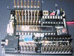
1) removed the 10k resistor pack and replaced it with a single line of chip sockets, now I can use the 10k resistors, or not, or change them for another is ever needed.
2) I will also remove the resonator and replace it with a 20Mhz. But I am going to also place three pins of an IC socket there to allow the resonator that I wish to be easily added or removed. I know that an external resonator is slightly more accurate than an internal, but I do not see that as a valid reason for having 4Mhz TWICE!!! I was appalled when I saw exactly what value it was!!
3) I see no reason as to why the bottom of the PCB has been cut to break the lands between the PICAXE chip and the ULN2803A Darlington driver chip. But other lands are in place on the component side. I managed
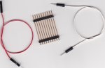
to fit a set of extra pins (similar to the output pins already used, but a single bank and far longer [ebay} so they are well above the top of the existing chips) in the set of holes left free between the PICAXE chip and the
Darlington Driver, which allows me now to be able to tap off the PICAXE “B” Port pins directly and not have to use the inverted signals of the driver chip!!! The soldering was a little difficult with my eyes, but it works really well.
I am interested in your thoughts on these areas.
Regards
Andy
I am using a PICAXE 28X1 chip in a 28 Pin project Board by the way.
As I have a background in computers, though the first one was in the 1960’s, but was only an onboard missile guidance system for RN Destroyers, about as big as a small house!!! I did imagine that after my almost 40 years work as a technical specialist and my programming knowledge, that I would find PICAXE easy. How wrong I was!!!!
I might agree that my age plays a role (I’m almost 68!)……
On looking back over this short time, I do notice that the supplied learning tools area little incomplete, but I do understand that it is a gargantuan job to get such Tutorials written and tested, and I do not mean that as a negative critique, more as a positive one, really!!
I worked through the easy stuff, making a LED blink etc., but I then found that the programs that I studied, for example, to read an RTC chip and display the time on an cheap 2004 type LCD display, were
fraught with problems, not of the PICAXE itself or even the programs I looked at were actually at fault, but the REMed comments were generally somewhere between bad and awful…. Very unhelpful.
Few of the programs (none that I have seen!) even put the PICAXE chip type in the program for which it was originally written! None mentioned which PICAXE pin should be connected to what pin on the LCD, except for a really good website (in NZ I think!), who not only correctly mentioned which PICAXE type it was written for, but also placed a correct schematic nearby and even mentioned in REMs which
connections should be made!! For beginners like myself FANTASTIC, I can only recommend the website of Technical Tutors:-
http://technologytutor.co.nz/introduction-to-electronics
Previously, all I had was Syntax Checking using the PICAXE Editor was one of the few ways to get things going.
May I make a request for the future to anyone placing PICAXE programs anywhere online for General usage that they adhere to at least the following requirements:-
1) Quote the exact PICAXE chip type that the program was written for in the format “#PICAXE 28X1” or similar for example.
2) That the program includes a REMed list of what each line is required to do, or be. Full details, especially Variables need to be carefully detailed how/why/what.
3) That the pin usage of the PICAXE is fully listed in REMs, no more guesswork!
4) A schematic is added, even for simple circuits.
I can say that the LCD examples in the PICAXE Manuals were more of a hindrance than a help, sorry, I took a long time to understand that.
The Chinese LCD display that I bought off ebay was cheap(!):-
a) not I2C as it actually said in the ebay ad. (Watch out for that, the seller is call “emall-foryou” (not my spelling error. It should have warned me!!). Leave him/her well alone. I asked for a schematic as they maintained that it was I2C compatible [its not!!] and got a dimension drawing, they haven’t a clue!!!)
b) Could have been defective, I could not prove it either way with my massive lack of knowledge.
c) Even the contrast control that I made could have been wrong!
But I did get it to work eventually and was able to place my full name 4 times on the screen!!! What a wonderful feeling!!!
I had already got a RTC readout program to work on I2C with the aid of several people here, but it was little of my own work.
Furthermore I have made some (I feel) useful changes to the 28 Pin Project Board, which may help
here, though maybe its already been done by some. I feel that they could be included on all
boards with only a small extra cost……
1) removed the 10k resistor pack and replaced it with a single line of chip sockets, now I can use the 10k resistors, or not, or change them for another is ever needed.
2) I will also remove the resonator and replace it with a 20Mhz. But I am going to also place three pins of an IC socket there to allow the resonator that I wish to be easily added or removed. I know that an external resonator is slightly more accurate than an internal, but I do not see that as a valid reason for having 4Mhz TWICE!!! I was appalled when I saw exactly what value it was!!
3) I see no reason as to why the bottom of the PCB has been cut to break the lands between the PICAXE chip and the ULN2803A Darlington driver chip. But other lands are in place on the component side. I managed
to fit a set of extra pins (similar to the output pins already used, but a single bank and far longer [ebay} so they are well above the top of the existing chips) in the set of holes left free between the PICAXE chip and the
Darlington Driver, which allows me now to be able to tap off the PICAXE “B” Port pins directly and not have to use the inverted signals of the driver chip!!! The soldering was a little difficult with my eyes, but it works really well.
I am interested in your thoughts on these areas.
Regards
Andy