Burglar Alarm.
- Thread starter the old fart
- Start date
To save a lot of repetition, see this fairly recent thread (and maybe put related discussion there). Personally, if/when I were designing an analogue keypad interface, I'd try the values I suggested in #37 of that thread, because they offer the potenial for an interrupt-driven keypad entry routine. However, an alarm system is sufficiently "slow" that a normal polling loop including the code you listed, will probably work well enough (but may need the key thresholds optimised for your specific build).I'm experimenting with this, previously published, circuit........ thoughts please.
I won't get involved in the overall "alarm system design" discussion, but IMHO the key factors are "absolute reliability" and "easy to use" (so both KISS), "psychology" and (ideally) identifying the culprits.
Cheers, Alan.
the old fart
Senior Member
I only want to use this on the 'outside' circuit that goes to the garage.From the little reading I did, I thought the purpose of the ADC was to be able to detect a specific type of tampering--shorting of the leads to the sensor.
I can't really see how likely to happen this contingency is when the sensors are inside the building to be secured.
Inside circuits are 'on' or 'off'.
It is perhaps worth highlighting that the commercial "FSL" scheme, with resistors in series and parallel across the contacts, allow detecting four states using just two wires: contact open, contact closed, wiring cut, wiring short.I only want to use this on the 'outside' circuit that goes to the garage.
Inside circuits are 'on' or 'off'.
That's not only useful for tamper detection, but for system integrity ... faulty wiring runs are detected. This detection is normally active even when the alarm is set inactive.
If you decide you will never get mice nibbles, water ingress, pinched, pulled or nicked cables etc., you won't need it.
lbenson
Senior Member
"FSL" is a new term to me--"fully supervised loop". And I see now its utility in detecting faults, not just intrusions.
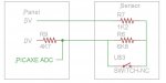
I'm still uncertain about the description to be found on the h'internet with the resistors both in the sensor (one a shunt across the n/c switch, and the other in series with it), with "the panel" detecting the condition. Here is a quote for 2K2 shunt and 4K7 series: "with the switch shut the panel will read 4.7k and with the switch open it will read 6.9k".
How does the panel (e.g., a picaxe) make this reading? Another series resistor to 0V, with the picaxe taking an ADC reading off of the end of the resistor which is not attached to 0V?
So in the attached circuit, with a 6K8 shunt, 1K2 series, and 4K7 to 0V, the picaxe reads 5V if the sensor leads are shorted, 0V if they are cut, 1.85V if the switch is closed, and 3.98V if it is open. Is this how it is done? I just guessed at the R values--what is standard?
Attachments
-
 46 KB Views: 25
That is very much how it is done. There's no set standard, else it would be easier to tamper! but all your guessed values are absolutely typical. Resistances in that range leave the cable run lengths and contact resistance negligible in comparison.So in the attached circuit, with a 6K8 shunt, 1K2 series, and 4K7 to 0V, the picaxe reads 5V if the sensor leads are shorted, 0V if they are cut, 1.85V if the switch is closed, and 3.98V if it is open. Is this how it is done? I just guessed at the R values--what is standard?
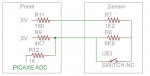
You might choose to have one of the external wires the 0v one, and the other fed via a resistor from the supply, simply to limit risk in case of external shorts - the short might be to building earth. Or both wires via resistors, which allows more error detection combinations and less risk from suprise inputs.
You'd want a resistor between the FSL proper and the Picaxe ADC pin, and really protection diodes to power/gnd rails, in case of unexpected input voltages - you might get 12v or negatives up there in a fault situation.
lbenson
Senior Member
Thank you, rossko. I hope this line of investigation is not too much of a hijacking of this worthy thread. So would 100-180 ohms be suitable in series out from 5V, and 1K to the picaxe, as in the attached circuit?
Exactly where do the protection diodes go, and what kind of diode?
Exactly where do the protection diodes go, and what kind of diode?
Attachments
-
 53.3 KB Views: 20
toxicmouse
Senior Member
Nice thread. I don't want to comment on crime tactics as it really depends on local crime trends.
I would save on all the wiring and have 2 PIRs in the passage. If both PIRs trigger then send a message by mobile. This limits false positives and dramatically simplifies code and hardware. Note that PIRs work best from a distance so creative positioning is required.
The garage could only have 1pir but 2 is better.
In my opinion PIRs are better than window sensors as they cover a wider range of situations. What if the thieves come through the roof or cut the putty/seal around the glass?
ADC input protection has been covered by greater minds than mine e.g.
http://www.picaxeforum.co.uk/showthread.php?19086-ADC-pin-protection-from-overvoltage
just saying it would be a smart idea where external wiring runs are involved
http://www.picaxeforum.co.uk/showthread.php?19086-ADC-pin-protection-from-overvoltage
just saying it would be a smart idea where external wiring runs are involved
lbenson
Senior Member
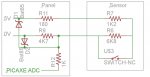
Ok, if, in the thread linked to by rossko57, I understand what womai and dippy were saying, and the diagram by goeytex, then adding the bat85 clamping diodes to the picaxe ADC input as shown in the attached circuit should do it: detection of cut lines, shorted lines, sensor switch closed or open, limitation of current if 5V shorted to house ground, protection of picaxe from overvoltage and undervoltage within reason.
Attachments
-
 64.6 KB Views: 14
I would jiggle it a bit, move the junction of the potection diodes to the Picaxe pin that they are protecting, the other side of that 1K resistor. That resistor limits current through the diodes, protecting them too (and whatever got accidentally shorted).
The other resistor values can be juggled for best effect, just so long as it results in easily distinguished voltages. Personally I'd be putting the lower value series resistors in the 'earthy' side.
The other resistor values can be juggled for best effect, just so long as it results in easily distinguished voltages. Personally I'd be putting the lower value series resistors in the 'earthy' side.
lbenson
Senior Member
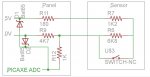
>move the junction of the potection diodes to the Picaxe pin that they are protecting
Doh! That was what I intended, and thought I had done. Here's the revision. Noted that resistor values can be juggled as desired.
Doh! That was what I intended, and thought I had done. Here's the revision. Noted that resistor values can be juggled as desired.
Attachments
-
 67 KB Views: 35
In a previous house we installed a commercial system in which the only perimeter sensor was on an the most obviously tempting entry window, and that was after some argument with the installer who of course wanted more work. Internally, I organised PIRs on the basis that a fair few rooms are uninteresting and others are for practical purposes inaccessible except from within the house. For example, if you want to enter the bathroom to steal our towels or even the kitchen to make off with a refrigerator packed full of cutlery, well, go for it. However, you could not by any discreet means enter a room of interest without detection.I would save on all the wiring and have 2 PIRs in the passage. If both PIRs trigger then send a message by mobile. This limits false positives and dramatically simplifies code and hardware. Note that PIRs work best from a distance so creative positioning is required.
In my opinion PIRs are better than window sensors as they cover a wider range of situations. What if the thieves come through the roof or cut the putty/seal around the glass?
the old fart
Senior Member
I want to monitor the 12v battery voltage.
I have a 10K0 and a 22K0 resistor to reduce the 12volt so the picaxe can read the voltage safely.
Should I add any further protection to the circuit?
--12vdc---------------22K0-----ADC input---------10K0----------0v
thanks
I have a 10K0 and a 22K0 resistor to reduce the 12volt so the picaxe can read the voltage safely.
Should I add any further protection to the circuit?
--12vdc---------------22K0-----ADC input---------10K0----------0v
thanks
the old fart
Senior Member
Circuit to garage,
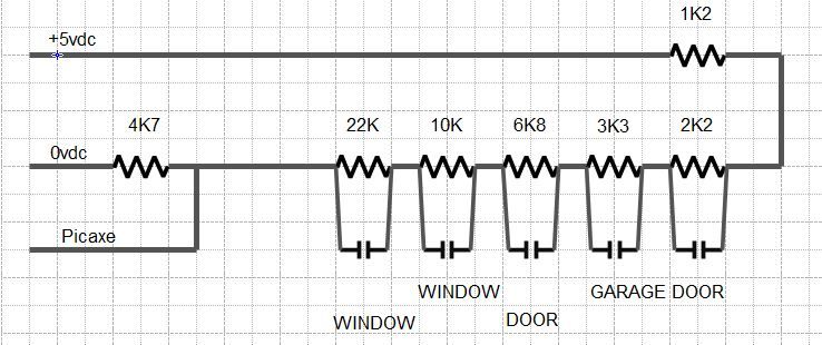
plus tamper circuit.
Value of adc gives indication of which switch has been operated.
plus tamper circuit.
Value of adc gives indication of which switch has been operated.
StigOfTheDump
Senior Member
If I'm reading this correctly, opening/closing the 3k3 and 6k8 switches would give a very similar ADC to opening/closing the 10k switch.
Stig, I would have thought that Old Fart's routine was so fast that 2 (or more) events would have to be impossibly coincidental to worry about.
And I haven't checked the figures but if values are stored after triggering he could plot the path of Burglar, though I agree O.F. should be a bit more mathematical about resistor choice. I have a feeling that someone looked into this more deeply before... was it the Sea of Keys?
Jim, I'm a one for KIS so I can't see how a second micro helps in terms of reliability, it would certainly help flexibility assuming soft and hard are properly designed. Whilst I prefer digital (as in on/off) Oldus Fartus is dead-set on analogue so I hope he keeps his connections clean")
And I haven't checked the figures but if values are stored after triggering he could plot the path of Burglar, though I agree O.F. should be a bit more mathematical about resistor choice. I have a feeling that someone looked into this more deeply before... was it the Sea of Keys?
Jim, I'm a one for KIS so I can't see how a second micro helps in terms of reliability, it would certainly help flexibility assuming soft and hard are properly designed. Whilst I prefer digital (as in on/off) Oldus Fartus is dead-set on analogue so I hope he keeps his connections clean
the old fart
Senior Member
The two window resistors could be higher value, as you have noticed it, what values do you suggest?If I'm reading this correctly, opening/closing the 3k3 and 6k8 switches would give a very similar ADC to opening/closing the 10k switch.
The switches are 'reed switches' which are sealed so shouldn't get dirty.
The bungalow sensors will all be digital.
In the event of a faulty garage switch, the adc value would immediatly indicate which switch was faulty.
StigOfTheDump
Senior Member
I wasn't commenting on your actual values, rather the fact that 2 switches both operated (or faulty) would give the fault code for a different switch. If you get burgled it won't make a difference, but if you are fault finding in 5 years time, it might.The two window resistors could be higher value, as you have noticed it, what values do you suggest?
the old fart
Senior Member
Hi Guys,
I need a bit of help with this part of the program,
bit0-7(b0) are the alarm inputs.
bit8=15(b1) are the alarm disable.
There must be a better way to program this.
I need a bit of help with this part of the program,
bit0-7(b0) are the alarm inputs.
bit8=15(b1) are the alarm disable.
There must be a better way to program this.
Code:
serout oled,baud,(254,134,#bit0,#bit1,#bit2,#bit3,#bit4,#bit5,#bit6,#bit7)
if b1=0 then goto skipX
if bit8=1 then serout oled,baud,(254,134,"X"):endif
if bit9=1 then serout oled,baud,(254,135,"X"):endif
if bit10=1 then serout oled,baud,(254,136,"X"):endif
if bit11=1 then serout oled,baud,(254,137,"X"):endif
if bit12=1 then serout oled,baud,(254,138,"X"):endif
if bit13=1 then serout oled,baud,(254,139,"X"):endif
if bit14=1 then serout oled,baud,(254,140,"X"):endif
if bit15=1 then serout oled,baud,(254,141,"X"):endif
skipX:

Thanks

TOFHi,
There might be lots of discussion about whether this is "better", but it's the way I've quickly hacked it together.
It requires a few extra variables (I've used b10, w10 and w11, but any will do, and they're only needed temporarily) and it seems to use about half the program space of yours.
Cheers, Alan.
There might be lots of discussion about whether this is "better", but it's the way I've quickly hacked it together.
It requires a few extra variables (I've used b10, w10 and w11, but any will do, and they're only needed temporarily) and it seems to use about half the program space of yours.
Code:
w10 = w0
for b10 = 134 to 141
	w11 = w10 and 256				; Read "Disabled" flag
		if w11 = 0 then
			w11 = w10 and 1 		; Read Status flag
				if w11 = 0 then
					w11 = "0"
				else w11 = "1"
			endif
		else
			w11 = "X"
		endif
		serout oled,baud,(254,b10,w11)
	w10 = w10 / 2					; Shift on to the next bit(s)
next b10Indeed. What makes one solution better than another; better source code readability, fastest execution, smallest program code size, smoothest display update, something else ?There might be lots of discussion about whether this is "better" ...
Here's another solution which works with PE6 ...
Code:
[color=Navy]#Macro [/color][color=Black]ShowBit[/color][color=Blue]( [/color][color=Black]stateBit, disableBit [/color][color=Blue])
  If [/color][color=Black]disableBit [/color][color=DarkCyan]= [/color][color=Navy]1 [/color][color=Blue]Then
    SerOut oled[/color][color=Black], [/color][color=Blue]baud[/color][color=Black], [/color][color=Blue]( [/color][color=Red]"X" [/color][color=Blue])
  Else
    SerOut oled[/color][color=Black], [/color][color=Blue]baud[/color][color=Black], [/color][color=Blue]( [/color][color=Black]#stateBit [/color][color=Blue])
  End If[/color]
[color=Navy]#EndMacro[/color]

[color=Blue]SerOut oled[/color][color=Black], [/color][color=Blue]baud[/color][color=Black], [/color][color=Blue]( [/color][color=Navy]254[/color][color=Black], [/color][color=Navy]134 [/color][color=Blue])[/color]
[color=Black]ShowBit[/color][color=Blue]( [/color][color=Purple]bit0[/color][color=Black], [/color][color=Purple]bit8  [/color][color=Blue])[/color]
[color=Black]ShowBit[/color][color=Blue]( [/color][color=Purple]bit1[/color][color=Black], [/color][color=Purple]bit9  [/color][color=Blue])[/color]
[color=Black]ShowBit[/color][color=Blue]( [/color][color=Purple]bit2[/color][color=Black], [/color][color=Purple]bit10 [/color][color=Blue])[/color]
[color=Black]ShowBit[/color][color=Blue]( [/color][color=Purple]bit3[/color][color=Black], [/color][color=Purple]bit11 [/color][color=Blue])[/color]
[color=Black]ShowBit[/color][color=Blue]( [/color][color=Purple]bit4[/color][color=Black], [/color][color=Purple]bit12 [/color][color=Blue])[/color]
[color=Black]ShowBit[/color][color=Blue]( [/color][color=Purple]bit5[/color][color=Black], [/color][color=Purple]bit13 [/color][color=Blue])[/color]
[color=Black]ShowBit[/color][color=Blue]( [/color][color=Purple]bit6[/color][color=Black], [/color][color=Purple]bit14 [/color][color=Blue])[/color]
[color=Black]ShowBit[/color][color=Blue]( [/color][color=Purple]bit7[/color][color=Black], [/color][color=Purple]bit15 [/color][color=Blue])[/color]the old fart
Senior Member
Thanks Alan, for your input.
Thanks Hippy,
I've never used '#Macro' before, but it works just great.
Cheers to both of you.
TOF
Thanks Hippy,
I've never used '#Macro' before, but it works just great.
Cheers to both of you.
TOF
the old fart
Senior Member
Progress.
here is the Keypad and 20x4 OLED display program to start with.
here is the Keypad and 20x4 OLED display program to start with.
Code:
; AXE134 Serial 20x4 OLED using PICAXE-18M2
; Emulates basic serial operation of the popular AXE033 module
; CPS, May 2011
; JB,  Jan 2012

#picaxe 18M2


; Supported Commands
; 0-7, 8-15	CGRAM characters
; 16-252	normal ASCII characters, according to selected character map table
; 253, X	display 12 character pre-saved message from EEPROM memory, X can be 0-11
; 254, X	OLED command, X can be 0 to 255
; 255, X	control outputs C.2, C.1, C.0 (via lower 3 bits of X)

#define use_welcome	; display the welcome message upon power up

symbol baud = N2400_16	; Serial baud rate 2400,N,8,1. Note main program runs at 16MHz

symbol spare0 	= C.0 ; spare output 0
symbol spare1 	= C.1 ; spare output 1
symbol spare2 	= C.2 ; spare output 2
symbol RX		= C.5	; serial receive pin
symbol enable 	= C.6	; OLED enable
symbol rs 		= C.7	; OLED RS

; OLED data pins are on B.0 to B.7

; Store the 20 character user defined messages in EEPROM data memory
; First two messages are optionally used as welcome message

; Please remember 4 line displays always use the strange 1-3-2-4 line layout.

EEPROM  00, ("     ALARM SET      ") 	; store msg 0 in the EEPROM memory
EEPROM  20, ("     ALARM RESET    ") 	; store msg 1 in the EEPROM memory
EEPROM  40, ("     ALARM TEST     ") 	; store msg 2 in the EEPROM memory
EEPROM  60, (" ALARM ALARM ALARM  ") 	; store msg 3 in the EEPROM memory
EEPROM  80, ("     GARAGE         ") 	; store msg 4 in the EEPROM memory
EEPROM 100, ("     REAR DOOR      ") 	; store msg 5 in the EEPROM memory
EEPROM 120, ("     FRONT DOOR     ") 	; store msg 6 in the EEPROM memory
EEPROM 140, ("     PIR OFFICE     ") 	; store msg 7 in the EEPROM memory
EEPROM 160, ("     PIR HALL       ") 	; store msg 8 in the EEPROM memory
EEPROM 180, ("     PIR LOUNGE     ") 	; store msg 9 in the EEPROM memory
EEPROM 200, ("     PANIC ALARM    ") 	; store msg 10 in the EEPROM memory
EEPROM 220, ("   ALARM SETTING    ") 	; store msg 11 in the EEPROM memory

;initialise OLED
init:
	gosub OLED_init 		; initialise OLED

; display welcome message if desired
#ifdef use_welcome
	let b1 = 11			; message 0 on top line
	gosub msg			; do it

	low rs			; command mode
	let pinsB = 192		; move to line 2, instruction 192
	pulsout enable,1  	; pulse the enable pin to send data.
	high rs			; character mode again

	let b1 = 11			; message 1 on bottom line
	gosub msg			; do it
#endif

; main program loop, runs at 16MHz

main:

	serin RX,baud,b1			; wait for the next byte

	; NB keep character mode test as first item in this list to optimise speed
	if b1 < 253 then
		let pinsB = b1 		; output the data
		pulsout enable,1  	; pulse the enable pin to send data.
		goto main			; quickly loop back to top
	else if b1 = 254 then
		low rs 	     		; change to command mode for next character
		serin RX,baud,b1		; wait for the command byte
		let pinsB = b1 		; output the data
		pulsout enable,1  	; pulse the enable pin to send data.
		high rs			; back to character mode
		goto main			; quickly loop back to top
	else if b1 = 253 then
		serin RX,baud,b1		; wait for the next byte
		gosub msg			; do the 16 character message
		goto main			; back to top
	else ; must be 255
		serin RX,baud,b1		; wait for the next byte
		let pinsC = b1 & %00000111 | %10000000
						; output the data on C.0 to C.1, keep RS high
		goto main			; back to top
	end if


; power on OLED initialisation sub routine
OLED_init:
	let dirsC = %11000111	; PortC 0,1,2,6,7 all outputs
	let dirsB = %11111111	; PortB all outputs

	; Winstar OLED Module Initialisation
	; according to WS0010 datasheet (8 bit mode)

	pause 500 			; Power stabilistation = 500ms

	; Function set - select only one of these 4 character table modes
	;let pinsB = %00111000 	; 8 bit, 2 line, 5x8 , English_Japanese table
	let pinsB = %00111001 	; 8 bit, 2 line, 5x8 , Western_European table1
	;let pinsB = %00111010 	; 8 bit, 2 line, 5x8 , English_Russian  table
	;let pinsB = %00111011 	; 8 bit, 2 line, 5x8 , Western_European table2

	pulsout enable,1  	;

	let pinsB = %00001100	; Display on, no cursor, no blink
	pulsout enable,1

	let pinsB = %00000001 	; Display Clear
	pulsout enable,1
	pause 7			; Allow 6.2ms to clear display

	setfreq m16			; now change to 16Mhz

	let pinsB = %00000010 	; Return Home
	pulsout enable,1

	let pinsB = %00000110 	; Entry Mode, ID=1, SH=0
	pulsout enable, 1

	high rs			; Leave in character mode
	return


; display message from EEPROM sub routine
; message number 0-11 must be in b1 when called
; uses (alters) b1, b2, b3, b4
msg:
	let b2 = b1 // 12 * 20		; EEPROM start address is 0 to 11 multiplied by 20
	let b3 = b2 + 20 - 1 		; end address is start address + (20 - 1)
	for b4 = b2 to b3			; for 20 times
		read b4,b1			; read next character from EEPROM data memory into b1
		let pinsB = b1 		; output the data
		pulsout enable,1  	; pulse the enable pin to send data.
	next b4				; next loop
	return
Attachments
-
 60.2 KB Views: 29
 -
4.9 KB Views: 16
Last edited:
the old fart
Senior Member
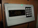
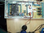
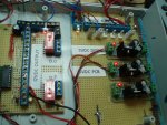
Here is the Remote Panel, and the Main PCB.
tri coloured LED shows Green,Red or Blue depending on alarm state.
tri coloured LED shows Green,Red or Blue depending on alarm state.
Attachments
-
 802.5 KB Views: 24
 -
 924.3 KB Views: 25
Last edited:
the old fart
Senior Member
Main program,
Still work in progress.
Line
14-102 set up bits descriptions
103-126 setup I/O descriptions
141 read saved bits from rtc eeprom
154 Main program starts
160 display clock
163 read key press
166 if key="#" then get code
174 cancel exit prealarm
186 selects which alarm setting required
196 if alarm is set then skip other options
208 Alarm walk is to test each point and display messages
213 latches alarm if in alarmset mode
217 displays which alarm mode is set 1-4
224 in alarm state, counts 11 cycles then sounds main alarms
230 removes : from display clock
232 checks sensors for activation
258 displays state of zones, 1=good, 0=tripped,X=turned off,D=disabled
276 chime on doors if enabled
284 save variables to eeprom
295 save incident to log, onboard 27LC512 at add1
310 end of main program.
313 reads 3 digit code from keypad, 999 returns if in alarm mode and codesub times out
336 codesub subroutine, loops until key <10
335 gets adc from keypad and returns key pressed
376 select which zones to set and Disables the rest
406 gets clock from rtc and displays on display
428 sets time and date to rtc
528 displays message stored in display and sets Green/Red/Blue LED
538 displays day
560 displays month
593 selects which zones to Disable 'X'
617 Writes incident data to Add1 eeprom
636 clears all the log, only used for testing, will be removed in final program
661 reads log on display 1-30 if garage alarm also displays ADC value
Chart showing words,bytes and bits usage.
I can't 'code' the program, too long.
Attachments
-
18.3 KB Views: 8
-
 260.7 KB Views: 16
Last edited:
the old fart
Senior Member
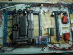
Main board.
40x2 picaxe mounted on AXE022P which plugs onto the board below.
25LC512 eeprom mounted on pcb
db3231 rtc clock module plugs onto board.
uln2803 interfaces portD to the 12vdc section
relays connected to D.0 & D.7 and provided voltage free change over contact. Up to mains voltage rated.
Power board
12vdc input at the top, with fused outputs, using poly fuses.
3 X 5vdc regulators, 1 for Main pcb, 1 for display, and 1 for something else.
regulators are overkill in size but were £7 for 5.
The complete unit is being run off a NP7-12L battery with a permanently connect SLA charger.
Attachments
-
 920.5 KB Views: 18
 -
 865.9 KB Views: 16
Last edited:
lbenson
Senior Member
Nice looking enclosure, and impressive work overall.
I particularly liked the layout sheet showing usage of bits, bytes, words, and pins--that makes for a good at-a-glance overview of what is often a jumble. I'll make up a similar spreadsheet for my next major project--and maybe even for an old one if I undertake a clean-up-the-code rewrite.
I particularly liked the layout sheet showing usage of bits, bytes, words, and pins--that makes for a good at-a-glance overview of what is often a jumble. I'll make up a similar spreadsheet for my next major project--and maybe even for an old one if I undertake a clean-up-the-code rewrite.
the old fart
Senior Member
Can you explain this line from your "Main Board" post:
"relays connected to D.0 & D.7 and provided voltage free change over contact. mains rated."
I particularly don't understand the part after "and".
voltage free contacts, is a changeover switch that can use any external voltage, like a relay.
altered post to read 'Up to mains voltage'.
relay around pcb have a 5mm gap and are coated with electrical insulating resin.
the old fart
Senior Member
Testing stage is now done,impressive, hope you can make it...
Just waiting for full enclosure for the circuit boards.
Anti-Tamper, Battery Check and a program tidy up completed.
I think!
TOF
Attachments
-
18.8 KB Views: 29
the old fart
Senior Member
Hope to hear from you, when it is done..
Just waiting for the enclosures to complete the project.