Please advise. 2 switches and 2 motors

adamg

Member
Bit of a newie question, sorry >___<

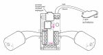
I have an AXE023 motor driver. I wanted to rig up 2 switches / buttons, and 2 Motors.

I later read the data sheet properly, after moving the jumpers around etc, and realised that you can only have either one motor and 2 switches, or 2 motors and one switch.

Does anyone know an easy hardware solution to have 2 motors (reverse and forward capable) and 2 switches all on the same board?

I need the smallest, cheapest option if possible.

The motors are small, and need to run off the picaxe power :)
 

westaust55

Moderator
Welcome to the PICAXE forum.

From the AXE023 Datasheet you can seemingly have 2 motors and two switches when the newer 08M2 is used. The second switch connects to pin C.5 and can not be touched during program Download or PICAXE startup. You need to use the DISCONNECT command before using the switch.
 
Last edited:

adamg

Member
Hey,

Thanks for your reply. That's what I thought. Even after moving the jumpers, following the protocol to have the 'disconnect' command at the beginning, the second motor only has a power supply when a switch makes the circuit. It's very strange.

can anyone verify that the AXE023 can have 2 switches and 2 motors connected at the same time?
 

westaust55

Moderator
Even after moving the jumpers, following the protocol to have the 'disconnect' command at the beginning,
the second motor only has a power supply when a switch makes the circuit. It's very strange.
Can you expalin which switch you are talking about.
The AXE023 datasheet does not include a schematic but there is no reason it should not work with the PROG-RUN jumper/bridge set to RUN and the other jumper/bridge moved to the right to segregate the second switch and connect instead to the C.5 pin.

Maybe a good quality photo of both sides of you board taken on a plain background and at right angles (perpendicular) to the board would be helpful to check for soldering, connections, circuit board defect, or other matters.
 

adamg

Member
It is a strange one. I have tried on 3 different boards. Maybe it is some problem with my really bad programing skills (Or lack of). I will show you my program later, with a photo of the board - and explain what I am trying to do.

the program is only about 20 lines - so not too much can go wrong I would imagine?

1X AXE023
2X motors: http://www.picaxe.com/Circuit-Creator/Motion-Outputs/DC-Motor/
2X microswitches: http://www.picaxe.com/Circuit-Creator/Switches/Microswitch/
3X aa batteries: http://www.picaxe.com/Circuit-Creator/Power-Supply-Circuits/45V-Battery-pack/

I want to program to do this.

1) If microswitch A is pressed - it makes motor A go forward for 1 second.
2) When microswitch A is released - it makes motor A go backwards for 1 second.

3) If microswitch B is pressed - it makes motor B go forward for 1 second.
4) When microswitch B is released - it makes motor B go backwards for 1 second.

That is all I need it to do :)
 

adamg

Member
Hey,

Cheers for the help good people!!! ^^ You are superstars!

I checked my board again last night and all connections are fine.

Here is a little diagram of what I have wired up, and a simple test program - WITHOUT microswitches.

I wrote this just to test if the motors would work with the jumpers in the positions that were suggested in the AXE023 manual.

-------------
disconnect

Start:

high 0
low 1
wait 1
low 0
low 1
low 2
low 4
wait 1

high 2
low 4
wait 1
low 0
low 1
low 2
low 4
wait 1

goto start

end
------------

here is my wiring layout:
axe023.jpg

I get a strange pulse of power instead of 1 second on the motor on the 2 and 4 pins.

and it does this in forwards and reverse when I have changed the program.

Is there something I am missing?

Thanks so much for your help again!!! I really appreciate it!
 

westaust55

Moderator
Is the MotorB pulsing only while actually downloading a program, when first downloaded or all the time in lieu of a 1 second run period? :confused:

You say it happens when motor in forward or reverse but the code you post only covers running motors in one direction. :confused:

I have reworked your program code with some small subroutines which by the labels make it easier to understand what is happening. Untested but it should work (famous last words!)
Note also how I have indented the program so only the labels start at the first column on a line and different levels of looping/testing structure are indented which helps make the profram flow earier to follow.

Code:
Init:
	DISCONNECT

Start:
    DO
	GOSUB MotorAStop
	GOSUB MotorBStop
	WAIT 1
	
	GOSUB MotorAFwd
	WAIT 1
	GOSUB MotorAStop

	GOSUB MotorBFwd
	WAIT 1
	GOSUB MotorBStop
    LOOP 


end
;
; Start of direction control subroutines
MotorAStop:
	LOW C.2, C.4
	RETURN
MotorBStop:
	LOW C.0, C.1
	RETURN
MotorAFwd:
	LOW C.1 : HIGH C.0 
	RETURN
MotorARev:
	LOW C.0 : HIGH C.1
	RETURN
MotorBFwd:
	LOW C.4 : HIGH C.2 
	RETURN
MotorBRev:
	LOW C.2 : HIGH C.4
	RETURN
As you have an M2 PICAXE part, it is good practice to get into the habit of using the port.pin nomenclature for referencing the IO pins to help avoid confusion with earlier M parts and for definite correct IO use when on larger chips with two or more ports for IO pins.
 

inglewoodpete

Senior Member
the program is only about 20 lines - so not too much can go wrong I would imagine?

I want to program to do this.

1) If microswitch A is pressed - it makes motor A go forward for 1 second.
2) When microswitch A is released - it makes motor A go backwards for 1 second.
3) If microswitch B is pressed - it makes motor B go forward for 1 second.
4) When microswitch B is released - it makes motor B go backwards for 1 second.
There are 3 three aspects to your project. 1) The PICAX023 board, 2) your wiring to motors, switches, battery pack and 3) your software.

Firstly, the AXE023 board WILL do what you want but you have to get points 2 and 3 correct for it all to work. So microcontroller projects are rarely simple.

Your ambitions for your project are admirable but, for a beginner, too much to do all at once. I suggest you develop you software in stages. Get the motors working. Learn how switch-presses are recognised in your code (0 to 1 or 1 to 0?). Get switch-presses to affect motor operation and then add the timers for motor control.

Edit: I see you're heeding my advice before I'd even posted it! I'm replying during breaks at work. It took a while!
 

adamg

Member
Thank you so much!

Sorry I didn't get back sooner. I was playing around with the board.

Well, It seems that if 2 switches and 2 motors can be rigged up to it, I can't do it. I tried so many different ways.

So forget that.

Now I am looking for an alternate way to do this. As simple and cheap as possible.

Anyone know what the best board for a L293D motor driver would be? I only need up to 3.6v at 500ma maximum.

I thought the PICAXE-18 High Power Project Board might be a bit of overkill. I just need something that can run the 2 motors (Forwards and reverse) and 2 switches. Would the L293D motor driver be the best way for this?
 

westaust55

Moderator
What part exactly is not working?
The code I provided at post 7 was just to test motor directions.

Have you enhanced to add code to monitor the two switches?

Please post your own code as it currently stands.
 

adamg

Member
Hey :)

The test code was perfect, without the switches wired up, and when the jumpers are in the normal position. However, even the test code wouldn't work with the jumpers set up in the other position, to free up the other pin, and the switches wired in. I though I would test it like that, before changing the code. It just starts to act strange. I get weird pulses of power being sent to the motors.
 

MPep

Senior Member
to free up the other pin....starts to act strange. I get weird pulses of power being sent to the motors.
Most likely then you need more decoupling capacitors across the supply rails.
 

adamg

Member
I am using some test code kindly given to me by Westaust55

Init:
DISCONNECT

Start:
DO
GOSUB MotorAStop
GOSUB MotorBStop
WAIT 1

GOSUB MotorAFwd
WAIT 1
GOSUB MotorAStop

GOSUB MotorBFwd
WAIT 1
GOSUB MotorBStop
LOOP


end
;
; Start of direction control subroutines
MotorAStop:
LOW C.2, C.4
RETURN
MotorBStop:
LOW C.0, C.1
RETURN
MotorAFwd:
LOW C.1 : HIGH C.0
RETURN
MotorARev:
LOW C.0 : HIGH C.1
RETURN
MotorBFwd:
LOW C.4 : HIGH C.2
RETURN
MotorBRev:
LOW C.2 : HIGH C.4
RETURN
 

adamg

Member
As you see, it has no inputs, it is just to test the motors forwards and backwards :)

I am totally new to all of this. I am thinking that maybe it is the lack of capacitor across the contacts? That is something I didn't do. Would that screw it up? Or even damage it irreparably?
 

westaust55

Moderator
For the motor connected to terminals 0 and 1, the OUT-PROG jumper at the side of the 08M2 PICAXE chip must be set to OUT for that motor to operate.

A note from the AXE023 datashseet:
Noise Suppresion on motors:
Note that motors should be suppressed by soldering a 220nF polyester capacitor across the motor terminals to prevent electrical noise affecting the circuit.

Something is amiss but I cannot put a finger on it.
Can you post a clear photo showing the AXE023 board and the wiring to the motors and switches so we can check that you have it all wired correctly.
 

adamg

Member
I will post the pictures tonight as will give it another try, just to be sure.

I am going to find some capacitors after work :) for the noise suppression thing. the 220nF if I can find it - or if not, what is better? higher number or lower number. I am using 3aa batteries :)

I will send a pic tonight when I have set it all up again :D

Thanks for your unwavering help!
 

westaust55

Moderator
I am going to find some capacitors after work :) for the noise suppression thing. the 220nF if I can find it - or if not, what is better? higher number or lower number.
A polyester capacitor of a near value should suffice. Say 150, 180, 220, 270 or 330 nF would all be candidates.
 

adamg

Member
Awesome!!!

It is doing what you told it in your code now!!! It is finally behaving with the addition of the capacitors :)

If I add the switches, can I program it like this?

IF PIN3 = 1 THEN
GOSUB MotorAFwd
ENDIF

IF PIN3 = 0 THEN
GOSUB MotorARev
ENDIF

That way when it is pushed, it will go forward, and when it is released, it will reverse..

Would that work?

So happy that it is behaving now :) thanks :)
 

MPep

Senior Member
Good to hear that your circuit is now working.:D
As for the IF...THEN.... question, read the manual and try it out. IF it doesn't work, THEN try again with some mods.
 

adamg

Member
Yes :) I think I learned a lot from this problem. You are all superstars. Can't believe how helpful people are! :)

I know this is the super basic beginners stuff, but I really am enjoying it :) I will try a few different things today and look in the manual again and other people's code examples. See if I can figure something out :)

I will let you know how it all goes.

As a side note. I am actually using the motors as a test. I have some (latching) pulse solenoid valves. They are 3.6v, 500ma. They are SUPER quiet, and without rigging them up to the air, I couldn't tell what they were doing. They open and latch with a 0.1 second pulse, and close with a reverse polarity pulse. The motors, with a little bit of tape on the shaft, are easier to see what is going on. I tested one last night, rigged up to the compressor at 60psi. Workes a charm, with the same code, just changed the WAIT times for forward and reverse to PAUSE 100, and then added a WAIT 1 in between each blast of air.

I know that is not what these boards are for. But before I misused them, I thought I had better get it working with motors first, as that is what they are designed for!
 

westaust55

Moderator
Great to read that it is all working.

You may now want to consider using a few bit variables as flags so you do not keep sending pulses to the latching solenoids while a switch remains in a given position.
 

adamg

Member
Hehe, I feel like I'm a kid again.. Everything is new!

I just looked into bit variables - sounds like a nice solution! I have never heard of them before.

So I guess that it will store the fact that the solenoid just closed, and not try to close it again until it has opened. When it opens, it will reset the bit variable, and let it know that it is okay to send a pulse to close again? And vice versa?
 

westaust55

Moderator
Hehe, I feel like I'm a kid again.. Everything is new!

I just looked into bit variables - sounds like a nice solution! I have never heard of them before.

So I guess that it will store the fact that the solenoid just closed, and not try to close it again until it has opened. When it opens, it will reset the bit variable, and let it know that it is okay to send a pulse to close again? And vice versa?
Yes, that is pretty much how to do it.
If you reserve say byte variable b1 for bit variables as flags (keep in mind bit and byte variables overlap in memory) that will give you bit variables bit8 to bit15 to use.
 

adamg

Member
Well, I have managed to do it the simple way so far.

Finally, the finished project will have a small lever rigged up to the 2 micro switches, so they can't be pushed at the same time. That solves a lot of problems :)

Still, it won't stop me from learning about subroutines etc..

:)
 

adamg

Member
Ace :)

Just tested it with 2 Latching solenoid valves and 2 switches, plumbed up to 90psi. Works perfectly!

Thanks for all your help and patience people :)

So, I guess the big lesson I learned was, to read the manual, and if it suggests something, it is probably very important!

Because eventually, there will be 20+ motor driver boards all rigged up, and needs to run on batteries, what would the best solution to that be? It is an animatronics project for a carnival next year, so needs to be as light as possible.. Are there any really good rechargable batteries out there with enougth amps? Would this work? Or would it catch on fire? http://www.batteryspace.com/nimhbatterypack36v13ah3xfforev.aspx
 

rossko57

Senior Member
First mention of solenoid valves. Do you really mean motorised valves? These are slower acting, but the correct type will stay put with no power applied. That might be good for battery life.

Will you need to run a compressor? Car batteries are readily available ...

For running many identical drivers, you'd probably want to look into 'bus' and 'multiplex' techniques. Essentially you send all the same signals to all the drivers - really simplifies wiring. And then 'address' or select whichever individual driver those signals are intended for at that time. That's assuming you want some kind of central control rather twenty indepent switch/driver setups?
 

adamg

Member
Great! I will look at that site :) Thanks :) I am living in South Korea at the moment, so it doesn't matter too much where they are from. I still have to pay the import duty >___< I might be able to find something here in Korea - you would think they would have something eh? If I find something online, I suppose I can ask in a few shops if they have something similar.

rossko57: The Solenoid valves I am using are 'Latching' or 'Pulse' solenoid valves. They only need one 30 - 40 millisecond pulse to open it, it then latches. Then a 30 - 40 millisecond pulse with reverse polarity to close it again. So they don't need a constant supply of power.

For the air supply, we will use a diesel compressor on the back of a pick-up truck. We could also use the battery from the pick-up truck, but would prefer for it to be more independent :)

Here is my very humble code:
Code:
START:

disconnect


MAIN:


    IF PIN5 = 1 THEN
    LOW C.1 : HIGH C.0
    PAUSE 35
    LOW C.0, C.1
    PAUSE 1
    GOTO MotorARev
    ENDIF

    IF PIN3 = 1 THEN
    LOW C.4 : HIGH C.2
    PAUSE 35
    LOW C.2, C.4
    PAUSE 1
    GOTO MotorBRev
    ENDIF

    GOTO MAIN

MotorARev:
    LOW C.0, C.1
    pause 1
    IF PIN5 = 1 THEN
    GOTO MotorARev
    ENDIF
    IF PIN5 = 0 THEN
    LOW C.0 : HIGH C.1
    PAUSE 35
    LOW C.0, C.1
    PAUSE 1
    ENDIF
    GOTO MAIN

MotorBRev:
    LOW C.2, C.4
    PAUSE 1
    IF PIN3 = 1 THEN
    GOTO MotorBRev
    ENDIF
    IF PIN3 = 0 THEN
    LOW C.2 : HIGH C.4
    PAUSE 35
    LOW C.2, C.4
    PAUSE 1
    ENDIF
    GOTO MAIN


END
 
Last edited by a moderator:

adamg

Member
P.S.

I am opting for lots of separate boards, due to be being totally new to programming - and on the plus side, if something goes wrong with the electronics, the others should be fine as they are not connected :D --- That's how I will spin it anyway hehe :)
 
Top