Making wire length cutting machine, need coding help

MikeGyver

Senior Member
Making wire length cutting machine, need coding help *COMPLETED*

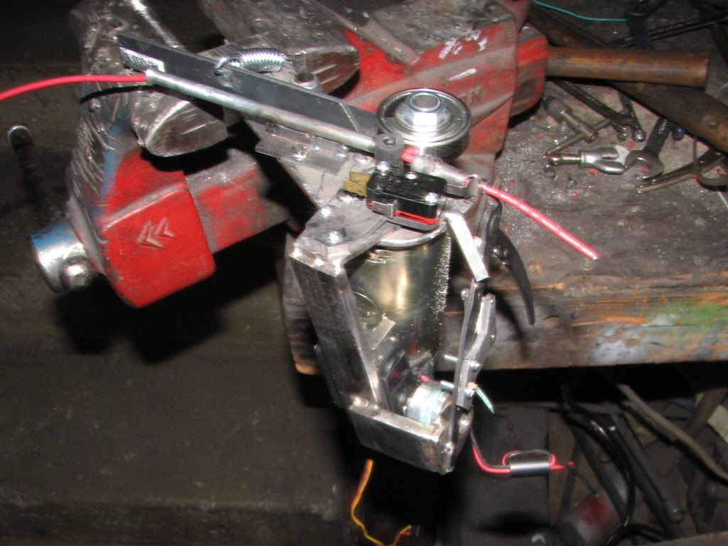
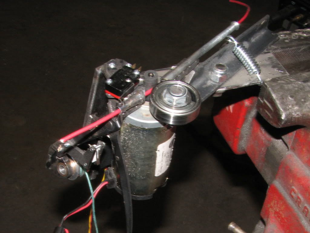
I'm making a machine that will quickly cut wire to length for me.
I'm basically done with the mechanical stuff now I need to start figuring out the and control software. I'm using a 28X2. Feed speed is quite fast, 2-4 feet per second.

Desired inches will be entered using a matrix keypad. The wire feeder will have a optical slotted disc to count pulses from the drive wheels. The entered inches will be converted into a target number of pulses.
I need to figure out the coding that will immediately brake the feed motor (with a high output) when the target number of pulses are seen.

Any ideas?
Can I use the 'count' command with a long time period and have an output go high as soon as the word variable fills up to the proper amount? Since I don't know how long it needs to count (different lengths of wire etc.) will it just sit there for the remained of the time duration?


Last edited:

SAborn

Senior Member
You could do all calculations first and have a small loop to count the pulses until the target is reached, something like...

start:

if pinX = 1 then
inc counter
endif

if counter = xxxx then
goto hit_the_brakes
endif
goto start

Only problem will be if pinX remains high then it will keep increasing the counter, so you might need to set a flag until pinx goes low again and clear the flag.

Im sure you will get more elegant code samples, but its a start.
 

inglewoodpete

Senior Member
I'd recommend you start by configuring hardware interrupts from the feed pulses. 2 to 4 feet per second is quite a feed rate. The interrupt routine would count interrupts and initiate the brake before cutting.

Lots of experimenting and chopped up pieces of wire to come!
 

matherp

Senior Member
Have a look at the settimer command in count mode. You need to connect the input to c.0 on the 28X2. You can then preload the 16 bit timer so that it interrupts when the requisite number of counts have happened.

Of course if you used a stepper motor the problem would go away :)
 

hippy

Ex-Staff (retired)
Something like SAborn's suggestion in post #2 seems best to me.

Alternatively you could calculate how long the motors will have to run for and simply turn the motor on, pause, turn off. Simpler but less accurate.
 

MikeGyver

Senior Member
Acceleration time shouldn't be an issue. the feed motor spins after you input a length, then you choose a wire color/size and insert it into the feeder. The rubber roller grabs the wire and spits it into the outlet wire guide where a limit switch near the cutters detects the wire and starts the count. Deceleration should be pretty constant so it might be easily accounted for in the programming by subtracting a few counts to every length that's input. The braking is handled with a SPDT relay that disconnects the motor from power and shorts the motors leads together. This brakes the motor surprisingly fast when running wire at 4ft/sec (24volts), within an inch or two of wire.
After the cut sequence the feed motor will reverse for a second to unload the wire so the next color/size can be inserted and cut to it's entered length.
This is to aid me in making automotive wiring harnesses at work and the accuracy & repeatability should be 1/4" or less.
 
Last edited:

MikeGyver

Senior Member
So use the settimer command in count mode; start running this in the background when the limit switch tells an input pin that wire is feeding. I don't really understand how to use this command based on it's description in the manual, but if it puts the incrementing count into a variable then couldn't I just do a DO until variable = x loop?
 

matherp

Senior Member
Mike

The beauty of the settimer count is that it does not "run" in the background, the counting is all done in hardware once initialised. If you don't need your main program to do anything but wait for the count then your do..loop while checking the count is perfect.
 

RexLan

Senior Member
On the practical side - my guess is that you will end up with a messy harness that will require a lot of dressing up to align it. 4'/sec is smoking and if you aren't making a few thousand of these a day for GM it seems to be much too fast to accurately control. Someone smarter than me can do the math but I don't think you can process the information, start/stop the thing and get a very good finished result.

You said the motor is 24V. If it is DC I would see if it will work (provide enough torque) down in the 8-12v range and slow the process up a bit like the wire feeder on the MIG welder.

Additionally, you may be able to drive the motor at almost any speed with a PWM signal while maintaining the 24V if it is needed.
 

SAborn

Senior Member
Your optical encoder will need to be on the idler wheel not the motor wheel to compensate for slippage.
I dont see 2 feet per second very fast, if all you want to read to is the nearest inch, as its only 24 pulses per second for 1 encoder target per inch. (i can almost count that fast)

The idler bearing looks to be about 1 inch dia, so 3.14 inch per rev, giving close enough to 3 targets for inch readings.
 

John West

Senior Member
While a stepper that can handle this job won't be cheap, it still seems like the best solution for software control code. The ability to easily control the feed rate and set the cut-off length for optimum precision would likely make it worthwhile considering just how many cables you wish to produce, and how fast it appears you wish to produce them. Otherwise, any changes in wire stiffness and insulations could cause things to get out of whack and may have to be adjusted in software.

I've worked much production in the automotive industry, and the simplest mechanical system design that allows for material variables is usually the best. In this case, that looks like a stepper motor. When you have to allow for this, that, and the other thing in software, you're creating possible problems that are best avoided from the start.
 
Last edited:

MikeGyver

Senior Member
On the practical side - my guess is that you will end up with a messy harness that will require a lot of dressing up to align it. 4'/sec is smoking and if you aren't making a few thousand of these a day for GM it seems to be much too fast to accurately control. Someone smarter than me can do the math but I don't think you can process the information, start/stop the thing and get a very good finished result.

You said the motor is 24V. If it is DC I would see if it will work (provide enough torque) down in the 8-12v range and slow the process up a bit like the wire feeder on the MIG welder.

Additionally, you may be able to drive the motor at almost any speed with a PWM signal while maintaining the 24V if it is needed.
24volts dc gives 4ft/sec, 12v gives 2ft/sec. 4ft/sec is blazing fast I'm going to begin at 12v until i get everything working. The motor will be PWM'd for variable voltage. Essentially im using a big 'servo' with feedback to dial in the wire length. Using a stepper motor has limitations. The rubber drive roller's diameter changes slightly with different wire diameters and changes in feed pressure, a stepper motor would drift if it was only driven by X number of pulses. Using reliable length feedback should be very accurate and only requre some coding to handle it all. And yes the encoder will be on the ball bearing which is 1.575" od (4.95" circumference). I'm not making this because it's anything I need by any stretch of the imagination, I'm making it because I'm bored and it's cool. If it's not fast it's not cool or worth making. If it doesn't impress me when it's done it will have been a big waste of time; and I'm using parts I had laying around, I don't have a big stepper motor.

I'm going to tinker with the settimer command today if I have time and see if I can figure out how to use it.
 

techElder

Well-known member
My 2 cents (which ain't worth a penny) ...

I would abandon the idea of stepper motors and encoders and timers. I would just put an optical gate out there where the end of the wire is. When the wire breaks that gate, activate the cutter. You can get pretty precise with that method. I know ... I did it long ago with nothing more than microswitches and a relay. I wish I had a microcontroller like the PICAXE then.

That "cutter" that you have in your mechanical pictures doesn't look like it is near good enough for the speeds that you want to attain.
 

MikeGyver

Senior Member
My 2 cents (which ain't worth a penny) ...

I would abandon the idea of stepper motors and encoders and timers. I would just put an optical gate out there where the end of the wire is. When the wire breaks that gate, activate the cutter. You can get pretty precise with that method. I know ... I did it long ago with nothing more than microswitches and a relay. I wish I had a microcontroller like the PICAXE then.

That "cutter" that you have in your mechanical pictures doesn't look like it is near good enough for the speeds that you want to attain.
Either I don't understand what you mean or you may be confused about the goal of this project. Every wire is a different length, size, and color. This machine is for quickly cutting out all the wires that make an automotive wiring haness. The cutter takes about 1 second. As soon as the wire is cut the feed motor will reverse and unload the wire and wait for the user to input a new length and a new wire; doing this will take longer than the cutter's 1 second delay so it's not the bottleneck anyway.
BTW, the modified R/C servo motor winch lifts 20 pounds vertically on 6 volts.
 

techElder

Well-known member
Yeah, missed the part about the on-demand variety. I've always just made bins of a certain length to pull from. My apology for confusing the issue.
 

Paix

Senior Member
I think that I'm sort of with TexasClodHopper, as even a short run of say six or ten makes a lot of sense - automation. Singletons don't need an automated system which has to be adjusted for the new length (from a selector) of every conductor, Better to have a flying spring clamp that grips the end of a new wire, "pulling" it along a rail and displaying the distance as it went. four or five preset lengths and a creep facility for final adjustment, then hit a manual cutter or a button to automatically cut. It would be more accurate - no slippage - and be easier to feed new wires and no slippage. The clamp could be arranged a bit like a dot matrix printer print head.

You only need an automatic machine when you really intend to automate things. I don't think that TCH need apologise for a predictable crystal ball malfunction :)
I can see that TCH would detect the desired end of wire travel and then cut at the feed point. So much less testing too.
 

SAborn

Senior Member
Firstly i think its great you got off your butt and attempted a solution to a problem, with what you had at hand to work with.
By the comments thus far it would appear in an ideal world everyone would have taken a different approach to the project. (thats common here from armchair critics )(or is that keyboard critics)

The bottom line is the mechanics is constructed and the question was," how to work with it from here in", after doing some calculations i dont think you will have a problem reading to the nearest inch, and i do like your method, although there may be some bugs it should still work to your required application.

It would be nice to see some picaxe solutions to the question asked,rather than how everyone else might build the hardware.

This knit picking of your present design only deters others to post pictures of their projects, which has long been a off forum gripe with this forum, and helps no one.

The OP asked for help with the picaxe side and not the mechanical build, so we should comment in that area, as the mechanical side looks sound and not made of cardboard and hot glue.
 

John West

Senior Member
More often that not, the folks here in the forum offer differing solutions simply because we are offered less input info than is necessary in order to make optimum project decisions about either components, code or both.

That often (usually, in fact) happens in a text based forum such as this, where little is known about the motives, needs, hardware and software experience of the designer, and funding and component availability for the project, and it's simply too much time and effort for them to produce all the relevant info. Such info would require pages of input. So, we stagger on as best we can with a bit of feedback as we meander along.
 

hippy

Ex-Staff (retired)
It would be nice to see some picaxe solutions to the question asked,rather than how everyone else might build the hardware.
I think that's generally been covered in the first few posts of the thread ( keep count of the pulses, stop when enough have passed ) and the rest has really been an aside of throwing up alternative possibilities which may, or may not, be worth exploring.

I don't really consider such discussion as criticism but well intended offering of suggestions and it seems to me a good indication that people are engaged and thinking about what the OP is doing and wants to achieve.

That's opposite to "Count the pulses. RTM", which may be what an OP sometimes wants but the OP can, and perhaps should, help steer the discussion, and subsequent discussion will usually follow their lead.

Hopefully any asides and wider discussions will be useful to the OP and even other readers, at worst must be ignored but hopefully not hinder progress.

I agree, it can sometimes feel frustrating when a thread does meander, and sometimes it needs a shake down or bringing back on track, but overall I think the enthusiasm shown in the forum is more beneficial than negative.
 

MikeGyver

Senior Member
I'm active on enough forums and share enough of what I build that I am used to a bit of "you shoulda have done this". It doesn't bother me too much anymore, especially when all the suggestions are ones that I've considered and discarded weeks before construction even started. If you don't like how how I'm building it, that's perfectly fine. Anyone is free to build their own, (but mine's going to work better :-D ).

Now for some good news...
I've written some code based on the settimer command and It looks like I've got it counting almost exactly how I want using a IR gate rigged on my breadboard. I've also tested the wire feeder electrical braking, when spitting wire out at blazing 4 ft/sec, it brakes the wire in .5" from when the wire hits the limit switch sensor, and this repeatability is appears to be under 1/16". It looks like I should easily be able to meet my 1/4" accuracy goal, and have an impressive machine that's much faster and cooler than anything comparable on the market.
I'm not necessarily trying to make a fool of the naysayers, but hey sometimes it just works out that way ;-)

I do however need help with some of the coding since I'm only a step or 2 above picaxe noob. I really appreciate further software help and help that has already been given.
 

inglewoodpete

Senior Member
I do however need help with some of the coding since I'm only a step or 2 above picaxe noob. I really appreciate further software help and help that has already been given.
It's great to read that you can consistently get the lengths you want. Ask away with your questions on code. Probably best to post the code you have along with the problems you are encountering.

In creating what appear to be 1-off wiring looms, what is your market? I'm assuming it might be (vintage) car restorations. Most other markets would want batches of replacement looms.
 

MikeGyver

Senior Member
In creating what appear to be 1-off wiring looms, what is your market? I'm assuming it might be (vintage) car restorations. Most other markets would want batches of replacement looms.
Hey thanks, I work at STS turbo ( www.ststurbo.com ), we make aftermarket turbocharger kits for late model 'muscle' cars (corvette, camaro, mustang, trucks, etc.). I make all the wiring harnesses that control our product (low quantity, a few various vehicle specific harnesses a day). Again this machine absolutely isn't necessary, just wanted to make something cool that's somewhat useful.
 

MikeGyver

Senior Member
Ok, I got it mocked up and it's working well :)

I made a crude 16 tooth encoder wheel out of paper and mounted it on the bearing, and I've got my 28x2 controlling the feeder so it will stop the wire at a pre-programmed length (after X pulses). I've got the feed motor running on 9volts in this test, so it's only running wire at about 1-3/4ft per second. because my encoder only has 16 teeth, the can only see wire in .3" increments. Repeatability seems to be about 1/8". I'm going to run probably 66teeth on the permanent encoder wheel, this will greatly increase the accuracy.

In this video I've got it programmed to count 16 pulses then stop. 16 pulses is 1 revolution, or 4.95" of wire. The actual wire length (not counting the constant 3/16ish" braking length) in this videos is right at 5.1". I've programmed in many different lengths and the accuracy remains the same.

View video here

 
Last edited:

SAborn

Senior Member
Very neat, i thought it would work well.

Seen you dont mind recycling parts for your projects, one thought for your encoder wheel would be using a salvaged encoder disc from an old bubble jet printer, often they have several encoder discs in them and also the laser led module, i have used several for projects and they work well, but the count might be too high as some can have 200 lines per inch, but others are lower lines per inch, you will just need to watch you dont overflow past 65535 in the count.
 

Svejk

Senior Member
Another way to make an encoder is to print it on a transparency.

Also, it may pay to check results with different wire gages. For increased control over the length you may control the deceleration, for example slow down when you have only 10" left to count.
 

MikeGyver

Senior Member
I found a website that generates optical wheels based on your specs. I'll print one and transfer it to metal and etch it or just print it on transparent sheet and tape it to a plexiglas base.

I plan on PWMing the motor mainly because the roller grips best upon insertion at lower speed. At 24volts it likes to burn the rubber and not grab the wire as easily. I should be able to program a simple decellerate function for the last few inches so the cuts are extremely accurate.
 

premelec

Senior Member
Ref to a codewheel generator program was made several years ago - on this forum - search the forum - small .exe file... the auto wire stripper comes next...
 

MikeGyver

Senior Member
Here's the web-based encoder wheel generator I used. http://www.bushytails.net/~randyg/encoder/encoderwheel.html
I made another test wheel today with 33 teeth which represents .15" of wire per tooth. The repeatability is better than +/- 1/16" on 12 volts now.

My matrix keypad arrived today from sparkfun (link) so I've been searching the forum trying to figure out how to use it. I understand the basics but I don't understand some of the code as I walk through it.

My goal is to be able to enter inches, store the number in a variable, multiply by however many pulses per inch and put in a new variable, then my pulse counting code will be able to handle it. I want the # key to act as "enter", and the * key to be a backspace/clear in case you mistype the inches. I also want an audible piezo beep anytime a key is pressed. All keystrokes will output to my serial LCD (also from sparkfun, 5v version of this link).
I'll keep examining some keypad code and see if I can make sense of it.
 
Last edited:

MikeGyver

Senior Member
Ok I've got some basic code written for my keypad that updates a variable with whatever digit is pressed, and beeps with each keystroke. I know there's some issues with the * and # keys for now and lots of dead ends, but we can ignore all that for now.

Here's kinda the main question. As an example, I'd want to be able to key in the sequence [2-4-7-#] (# being "enter") and have it set a variable to 247.
Am i on the right track thinking I'll need to have the 1st keystroke multiplied by 10 then added to the 2nd keystroke... and then the 1st x 100, 2nd x 10, and + 3rd, and so on for each new ones/tens/hundreds/thousands place? This way the number updates the least significant digit on the fly. So keying in [2-#] will set a variable to 2, and keying in [2-3-7-1-#] will set a word variable to 2371.

Code:
symbol key_value = b0
symbol piezo = c.4

init:
	let dirsB = %00001111

scan:
	debug
	let key_value = 0
	let pinsb = %00000001
	gosub key_test
	let key_value = 3
	let pinsb = %00000010
	gosub key_test
	let key_value = 6
	let pinsb = %00000100
	gosub key_test
	let key_value = 9
	let pinsb = %00001000
	gosub key_test2
	goto scan

key_test:
	if pinb.4 = 1 then add1
	if pinb.5 = 1 then add2
	if pinb.6 = 1 then add3
	return
	
key_test2:
	if pinb.4 = 1 then let key_value = 0 let b2 = 0 endif
	if pinb.5 = 1 then let key_value = 0 endif
	if pinb.6 = 1 then goto enter_inches
	return	

add1: 
	high piezo
	pause 50
	low piezo
	let key_value = key_value + 1
	let b2 = key_value
	return
add2:
	high piezo
	pause 50
	low piezo
	let key_value = key_value + 2
	let b2 = key_value
	return

add3:
	high piezo
	pause 50
	low piezo
	let key_value = key_value + 3
	let b2 = key_value
	return
	
enter_inches:
	`convert entered 0-4 digit number to pulses and use to measure wire
	end
 
Last edited:

techElder

Well-known member
Possible sequence of events?

... the feed motor spins after you input a length, then you choose a wire color/size and insert it into the feeder.... After the cut sequence the feed motor will reverse for a second to unload the wire so the next color/size can be inserted and cut to it's entered length....

Is this how the process sequences?
  1. Decide which wire to use
  2. Punch in the wire length on the keypad
  3. Find the wire size
  4. Find the wire color
  5. Physically grab the selected wire
  6. Feed the selected wire into the cutter
  7. Wait for the cut-to-length to reverse the wire
  8. Eject the cut wire
  9. Start over
 

MikeGyver

Senior Member
yes, so basically this:

you want 154" of 18awg white wire, for example
1. key in [1-5-4-#] (# being "enter"), beeps on all keystrokes and updates serial LCD
feed motor begins spinning
2. manually insert 18awg white wire
wire is pulled in then sensed on outlet side, pulse counting begins, fed to 154" then cut, feed motor reverses to unload wire from rollers
3. manually remove wire from inlet tube
4. ready to repeat
 

hippy

Ex-Staff (retired)
For the keypress handling I'd be tempted to have a single routine which returns when a key is pressed with a value 0-9 for digits, 10 for * and 11 for #, and 12 if nothing pressed ( or don't return until a key is pressed ). Then some control loop like ...

Code:
Symbol keyPressValue = b0
Symbol inches        = w1

Symbol STAR_KEY      = 10
Symbol HASH_KEY      = 11

Do
  Gosub GetKeyPress
  Select Case keyPressValue
    Case 0 To 9 
      inches = inches * 10 + keyPressValue
      Gosub UpdateLCD
    Case HASH_KEY
      Gosub UpdateLCD
      Gosub ChurnOutWire
      inches = 0 
      Gosub UpdateLCD
  End Select
Loop
 

techElder

Well-known member
OK, so after you get this part working, you must be planning on "staging" all the spools of wire into a similar tubular feed mechanism that would then feed each of the different wires into this measuring/cutting device for you.

I only bring this up, because you might be considering this expansion while you are developing the keyboard data entry routines by being able to add a wire number or size or some identifier to the length input. Just sayin' ...

yes, so basically this:

you want 154" of 18awg white wire, for example
1. key in [1-5-4-#] (# being "enter"), beeps on all keystrokes and updates serial LCD
feed motor begins spinning
2. manually insert 18awg white wire
wire is pulled in then sensed on outlet side, pulse counting begins, fed to 154" then cut, feed motor reverses to unload wire from rollers
3. manually remove wire from inlet tube
4. ready to repeat
 

MikeGyver

Senior Member
You mean like a gatling gun lookin hopper? lol it's very possible, maybe down the road some, for now I'm just trying to keep things simple and figure this out, then I can expand it once it's working.
 
Top