Hall sensor with engine, pulse in or count, please help.

davecarter

New Member
If any could help. just about to give up!

I have posted before but I did not get a resolution to this issue.

I am trying to get two rc engines to sync.

The first step is read the speed of both enignes.
I have decided to use a hall sensor fo this. I have a rig setup where the pulses from the hall sensor are read by an 18m2. I sarted by using a "count " command. But I felt that the accuracy was not going to be very good. So I have tried "pulsin". What I found is that, when the pulse is slow. ie 1000rpm (16 pulses per second) Other commands are affected. In fact when the pulse is high the servo still does not act as it should.

What I need to do is to use the pulsin variable to position a servo. The servo command in this case is unusable. The servo just goes nuts.
So what I thought is that I could generate a signal either a serial or varying voltage to send it to another picaxe which intern would read the signal and control the servo.
I have no experiance in generating a varying voltage or serial output which can be read by another picaxe.

Please help.
Dave.
 

SAborn

Senior Member
Dave you can just send a digital number from 1 picaxe to the other, the easy way is to send it as ascii data which requires you to use the # symbol before the variable with the data. ie: #b1 and then do the same on the receiving end.

If you can add more magnets (targets) then you response time will be greatly increased at lower rpm.
 

davecarter

New Member
Will the receiving of a serial signal halt the receivng picaxe program and cause a problem the the servo command.

Dave.
 

SAborn

Senior Member
Yes it will halt the program waiting on data but the 18m2 has a timeout function that you could keep short and keep looping to check for data, or use a extra pin so if pin X was high then go and read serial data.

I have never used servos to know if they will be effected when reading serial data.
 

Goeytex

Senior Member
Don't give up !

Dedicate one Picaxe to reading the hall sensor with Pulsin. It then send its data to another Picaxe that uses background serial receive that should not affect the servo command. Background serial puts the data directly into the scratchpad memory. You can also set the Picaxe ( X2 parts) to generate an interrupt as soon as the serial data is received. Or it can be read out at any time using @ptr. I used this method to develop an ignition system for for a 4 stroke 2 cylinder engine and it works very well. I used 20X2's.

I'll do some breadboard testing later today and see what I can come up with for you. So be patient. What I have on hand here is 28x1, 20x2, 18m2. 14M and 08m.

What Picaxe are you trying to use ? What is the max RPM of the engine ? Do you have a scope ?
(Ok I see ... 18m2) .... What frequency are you setting the Picaxe ? 4mhz or 16 mhz ?

Do me a favor. Run the engine and give me the pulsin value at approx 1000 rpm. Then reverse the polarity of the pulsin
command and give me that reading as well. In other words one pulsin < pulsin pin#, 1, w0> reads the on time and the other
< pulsin pin#, 0, w1) reads off time. If we add the two together we get a fair idea of time period, but in the end we will only use one of these as a relative speed value..
 
Last edited:

davecarter

New Member
View attachment ENGINE SYNC.pdf

Thank you so much for your help. I am trying to use an 18m2 at the moment. But my initial thoughts were to use two 8m2's for reading the hall sensors and then an m182 for the servos etc.
Please see attached sketch.
However if I need to buy different types of picaxe then i will.

Any assistance with the code will be greatly appreciated.
Dave
 

geoff07

Senior Member
I'm not sure what output you get from a Hall sensor, but if it can be a simple rising or falling edge, then why not use an interrupt? The interrupt would increment a pulse counter for each motor, and the main code would use the count to make appropriate adjustments. Interrupts are very fast and because they are invisible to the main code they make using the data very simple, and I suppose (without checking) that a servo would work normally. It depends on what rpm you are detecting, but the chips are so fast these days that a very short ISR would allow quite high pulse rates to be detected. This is how I detect motor stalling in my garage door controller, which detects 10cps very easily (I suspect rather more pedestrian than your app, but similar).
 

Goeytex

Senior Member
My guess is that the Hall Sensor has an open collector output. So the signal will be a square pulse.
At 10,000 rpm the engine makes 1 RPM in 6ms. At 1000 RPM that would be 60ms so I suspect
that using a counting method would be too slow to make engine throttle sync adjustments
in a timely manner. With pulsin you get a number nearly instantly that represents relative engine velocity.
So corrections could be made within one or two engine revolutions. That is not possible using count.

@Dave.

Please post the part number of your Hall Sensor or a link to the Datasheet.

I have two servos hooked up now and working good, and now working on the coding. I need to generate two signals that
simulate the Hall signal for each engine so I need the data that I asked you for in my previous post.

Goey
 

davecarter

New Member
Goey.
Thanks for the reply. I am using a hall sensor from a model petrol engine that i stripped down. I have not got a serial number for it as it is in a plastic casing. However i do know it is a non latching switch type, hall sensor. When i get back into the office i will select a hall sensor and post the data sheet. Thanks again.
Dave
 

Goeytex

Senior Member
This is fun.

I got my old ( 1982) RC Plane out of storage and robbed two of the servos out of it. They worked great with Picaxe
Servo first try. Set up two VCO's to represent the engine speed (Hall Signal) from 800 RPM (idle) to 10,000 RPM.
One servo controls the pot for VCO1 ( Engine1) and the other for VCO2 (Engine 2). The output of each VCO is
sent to a 4017 to simulate an approx 15% duty cycle that the Hall Sensor will likely produce ( depending upon magnet area)
This is working and is a pretty good RC engine simulation.


Engine 1 will be the master or control engine. The speed of Engine 2 will be compared to the speed of engine 1.
Picaxe Program will then adjust the speed of engine2 via "servopos" to match engine 1 within a few RPM. At least
that is the plan. Code details later.
 

Goeytex

Senior Member
Are you still with us Dave ?

I have been experimenting with several Picaxe chips to figure out the best way to do this and in doing so have learned some
of what works with SERVO and what doesn't. SERVO seems to glitch at constant rate when run at 16mhz on the 18m2. No
glitching at 4Mhz, all else being equal. Right now I have it working using a 20x2 to read both Hall Sensors sequentially
with pulsin and then compute the speed difference between the engines. Two bytes are sent to the 18m2, the speed
difference, and a byte that indicates if the slave engine is slower or faster than the master engine. These bytes are are
received in the 18M2 2 byte hardware serial buffer. A loop reads the bytes with Hserin and then adjust the slave engine
servo position based upon the speed error between the engines. So far so good.

Let me know when you are ready to continue.
 

davecarter

New Member
Goetex.

Sorry for the delay in reply.

Work, work, work!

You are a star.
I received a package of items from Picaxe (including 20x2 chips )on Friday, so the experimenting will resume tomorrow.
Dave.
 

Goeytex

Senior Member
Work ....I hear ya.

I had an arterial replacement / graft in my left leg on the 1st. ( FEM- POP). Just now starting to get around a bit.
But hey, it's given me some time to do some Picaxe stuff and catch up on my reading.
 

Goeytex

Senior Member
@ Dave

I have been testing and experimenting with the Picaxe Servo command, and at at this point have concluded that Picaxe "Servo" is not up to the task due conflicts with the other commands we need to send data between 2 Picaxe Chips. In all scenarios the servo(s) will glitch or jitter when serrin, hserial, or I2c is used to receive control signals. This is because of the way the hardware timer is used with SERVO, but is unacceptable in an accurate, glitch free RC engine control.

So SERVO and SERVOPOS have been abandoned in favor of using pulsout in a timed loop, making one Picaxe chip a dedicated I2C/ serial Servo Controller. I should have some code ready soon.
 

hippy

Ex-Staff (retired)
PICAXE are general purpose controllers so some things may be less than perfect where high accuracy or very fine control is needed without some thinking about how that system works and integrates with other parts.

With autonomous SERVO commands and unsolicited control signals coming in at any time there will always be the potential of some collisions and servo jitter. Sometimes that can simply be ignored, other times one gets lucky and the timing works out perfect so no jitter but sometimes one gets unlucky and jittering becomes more prevalent.

The best system is one where you take control of everything yourself so a PULSOUT/PAUSE loop has an advantage over SERVO. Other things may be lost with that but they are not important here.

Taking a servo position in over high-speed serial minimises the chance of a collision with PULSOUT and, just to be sure, you can have a window in which to accept such serial data ...

Code:
Do
  PulsOut pin, <servoPulse>
  High ALLOW_SERIAL_DATA
  Pause <20ms> - <servoPulse> - <2ms>
  Low ALLOW_SERIAL_DATA
  Pause <2ms>
  HSerIn <servoPosition>
  If any new <servoPostion> Then 
    <servoPulse> = <servoPosition> * K + C
  End If
Loop
Something like that on an 08M2 should give fairly rock-solid servo control, especially if the controlling PICAXE doesn't send data when it shouldn't. Even though the 08M2 is using high-speed serial the controller talking to it can use normal SEROUT.
 

Goeytex

Senior Member
Very close to what I was thinking. Was considering using a 20X2 at 32 to 64 mhz to make a 4 to 6 channel servo controller.
Initial testing last night using pulsout has shown excellent resolution and smoothness in moving these very old JR servos. Using pulsout at
32mhz gives about 1200 steps instead of Picaxe Servo's 150.
 

RexLan

Senior Member
Possibly I missed the idea but as a practical matter do you think this will actually work in an RC engine that can rev to 10K RPM in a second or less? What about the servo linkage to the engine .... 0.001" change could be +/- 200 RPM can't it? I don't understand the mechanical interface yet.
 

Goeytex

Senior Member
You will only know if you try.

The .001" per 200 rpm is not a very realistic number. That would mean only .050" lever movement from 0 - 10,000 RPM.
There is a lot more than that and it will vary from engine to engine and how the mechanical linkage is set up.
I would think more in degrees of shaft rotation than in distance.

The Picaxe can update the servo position every 20ms. If by your guesstimate that the engine can rev from 0 to 10,000 rpm in 1 second
over that period of time the servo position can be updated (1000ms / 20 ms) or 50 times. So I think it's doable. We are gonna find out.
 

RexLan

Senior Member
I agree it is a challenge and fun to design!. However, I just question the practicality if that is really OP's intent and need. If it is just for fun then that is a different matter.

I have no idea if 0.001 or 0.100 will change the RPM by X or Y ... I was only suggesting that this will be a VERY fine adjustment. I suspect that the "controller" will always be behind it, especially as the load changes, and it will tend to oscillate requiring some hysteresis or averaging of the input data (RPM) to smooth it out which or course will cut the update correction by a huge factor further compounding the problem.

Would typical shaft rotation be ~ 90 degrees from closed to wide open? If so, perhaps with some gears you could get pretty fine resolution on the shaft.

If we are going to subsequently add an RF link to it I wonder how that will factor in?

Are you going to use a linear or angular servo and what is it's resolution?

I read this .. can not verify it however:

"If you put a 4"/10cm arm on a standard (+/-60 degree) servo, 1 microsecond change in pulse width (usual max resolution of computer transmitters) gives about 1mm of movement at the end of the arm."

Let's get it working!
 

Goeytex

Senior Member
Per the OP ..... "I am trying to get two rc engines to sync. ... The first step is read the speed of both engines."

Granted there are a lot of details missing from the OP. We don't know is there is an RF link or what type. I am assuming that since idle
speed was mentioned that the engines are piston type liquid fuel based. We don't know the max Rpm of these engines or the mechanical
setup. We don't know if the servos are angular or linear.

But some of this is not relevant for what I am doing, and that is proof of concept and to help the OP get going in right direction.
A side result may be a 4 chanel Picaxe based Servo Controller using I2C or serial com. I saw a PIC version selling for $16.95 US
but if I can do this with Picaxe, I'll post the code here.

With my testing setup I can simulate any engine speed and range using a pot connected to each servo supplying a voltage
to a 74HC40406 then to a 4017. The output represents the Hall Sensor output. So as the servo moves full range the simulated hall sensor
pulse width follows. This is read by pulsin, each engine revolution. The maximum lag in processing is 3 engine revolutions given
a minimum RPM of 800, a servo signal every 20ms, and I2C communication between the two Picaxes.

Figuring in an RF link doesn't change much since we have an 18ms window to do stuff without interfering with the pulsout servo signal.
My JR servos work fine with 30 ms between pulses but I suspect that others may not, so I'll stay with 20ms as a standard.

I am testing with angular servos but the concept remains the same, engine 2 syncs up with engine 1 based upon the difference in rpm.
Will know more later.
 

davecarter

New Member
My problem initially started when trying to read the hall sensors with the count command. This turned out in many areas not be suitable. I calculated the ability to read the rpm to be no better than about 200rpm.

So if the reading of rpm was so far out, then the we get off to a very bad start and there is no correcting that in the future.
So I tried the Pulsin which can ultimately can read an accurate rpm, but then reading this successfully whilst carrying out other commands like "servo"etc was a major issue, and this is when a called for help.

A point was mentioned about the servo arm length, on an rc engine this should be quite small in the region of 10-15mm, and the rotation angle will depend on the engine it is connected to(however we always try to get a rotation angle of 90 deg).
When we setup a twin engined plane. Normally the engine rpm is set at full throttle using an optical meter. These are not that accurate, and the resolution of the read out i think is no better than +/- 100rpm. The mid throttle rpm is harder to set. However I have a transmitter that can set throttle curves for both engines’ individually, this makes things a little easier.

So in conclusion, the reading of rpm has be as accurate as possible, as there will always be in accuracies through the control system, however i think +/- 50 rpm should be final goal.
Dave...thanks for your continuing help.
 

davecarter

New Member
Geoytex

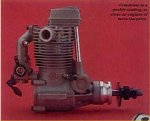
The engines in question are glow fuel 4 stroke's find attached pictureasp70_fs_mp2.jpg

These engines would normally tick over at 2500-3000 rpm. with a max of about 9000-10000 rpm.

I am sorry if I did not mention it earlier, there will be a signal coming from an rc receiver to set the rpm of the engines.
The engines will not throttle equally. Hence the need to sync the engines by other means.
Also if opne engine cuts out then the other also has to drop to idle, this will prevent the plane from snapping into a spin.

Dave.
 

davecarter

New Member
just another thought.
I found this item on the web

http://www.hvlabs.com/serservo.html

This item can control a number of servo via a serial signal from a pc.

I emailed him:

>
> Message:
> hi,
> just been reading your website. its great.i have a question is there
> any way your code will work with input from a serial output from a pic
> such as picaxe.
> Dave

Reply:

Hi Dave,

Yes it is possible, anything that can communicate with serial and hardware handshaking can control the ssc board. See the attached text file about how to control the outputs.

Hope this helps.

Oliver

www.hvlabs.com

I looks like this could be the perfect companion for the picaxe serial signal but I have no idea how to generate the singals the it need.
What does the forum think.
Dave.
 

Goeytex

Senior Member
Dave,

Q1: Do you have an Oscilloscope ?

Q2: Please explain how the engine throttle linkage is connected. Is there a separate servo for each engine? ...
or are they mechanically connected and operated by a single servo ?
 
Last edited:

Goeytex

Senior Member
I see the diagram but where is the receiver ? How does the control signal to get to the Picaxe?
The diagram only shows a partial system. The more details the better.

Does the RC TX have separate control ( Stick?) for each engine servo? If not. please explain how
it currently operates the throttle.
 
Last edited:

davecarter

New Member
Ok. The current setup is...
One servo is connected to each engine via a direct link to the engine.
Each servo takes a seperate signal from the rc receiver. The signals from the transmiter sends individual signals to each sevo. This enables me set the endpoints of each servo.
Dave
 

davecarter

New Member
Sorry I forgot to mention. One stick controls both both servos. The transmitter then sends two seperate signals, one to each servo.
Dave
 

Goeytex

Senior Member
So that we are very clear, there are two channels for engine control operated by one stick on the TX.
That should mean that you can kind of balance the engines from the transmitter. Right ?

Therefore there are two separate outputs from the receiver for engine control. One set of 3 wires for each engine.
In other words there is NOT a single output from the receiver that is split and sent to each engine.
 

davecarter

New Member
Goeytex
The setup i have at the moment. Will not sync the engines nor will it monitor both engines to detect if one engine has stopped. The picaxe sync should only need one reciever input. Which both engines could follow.
Dave
 

Goeytex

Senior Member
There are several ways it can be done. One input, two inputs.... Lots of bells and whistles or basic syncing.
 

Goeytex

Senior Member
That's the plan. What the system will have to do is read the receiver throttle signal and the two speed sensors. Then convert the receiver signal into two servo signals where the engines are sync'd within 50 rpm or so. The tricky part of this is the timing of signals between the Picaxes.

I now have a new simulator built that will speed things up.

One 10K pot simulates the transmitter throttle control. This ADC goes to a 08M and is converted to a servo signal which accurately simulates the receiver output.

This servo signal (pulse width) is read by a 20x2 and stored in memory. The Speed signals are also read and stored. These datas bytes are sent to another Picaxe which does the math and then sends out 2 servo signals where the engines are sync'd. Working on the timing and math now.
 

Goeytex

Senior Member
@DAVE

I had wanted t0 use IC2 for com between Picaxes but it seems there is a bit of a problem using I2C and pulsin at the same time on a single Picaxe. With a 20x2 and I2C initially setup, one of every 8 or so pulsin reads is corrupted by something that I2C is doing in the background.

This causes glitches since the pulsin value is used to generate the servo pulses . Possibly I2C could be turned on / off and only used in a window to prevent this but it becomes a timing challenge. I do have the Picaxes talking and sending serial data using 1 throttle input and 2 hall speed inputs. Doing this with serin / serout and interrupts. The challenge is dodging and getting around timer conflicts with the commands we need to use. ... More later.
 
Last edited:

davecarter

New Member
Goeytex.
Thankyou so much for trying so hard to sort this out. I had a thought... What about generating a dac from a 8m2 (one per hall sensor) then reading that voltage with another picaxe to do the servo commands. I do know if the 32 steps on a dac coukd be increased to improve the resolution.

Dave
 

Goeytex

Senior Member
The 32 steps is the limit with Picaxe DAC. The resolution would not be good enough to get engine sync very close .... 350 rpm maybe.
Not worth pursuing IMO.

I think I may be pretty close to having a working prototype syncing up using 2 18m2s and 1 20x2 using a master slave
technique. using only one servo input from the receiver helps to simplify things. But it seems every time I can use a
particular feature, the M2 parts are missing what I need. Hardware interrupts only on X2 parts ... Only X2 or 28X1 can
be I2C slave... (no scratchpad on M2) ... A 14X2 would be cool ...

The manual 2 indicates that "pauseus" is not supported on M2 parts, but it seems that it really is. That's good.

Can only give this about an hour per day .... but getting there.
 
Top