Siemens A55/C55 LCD graphics display

westaust55

Moderator
Compass display using the A55 gLCD module

For my current project to use the A55 gLCD as a display for the CMPS03 compass module, I have been a little quite for the last few days. Did encode a single compass image at the proposed size of 56 pixels on x-axis x 48 pixels on y-axis and it came up as a good representation of a circle. Recently have been mulling over more memory efficient methods of achieving the desired goal.

After some thought I have identified that by adding some maths to the compass rose plotting routine, as opposed to just a straight copying of bulk image data from EEPROM, that I should be able to reduce the EEPROM memory requirements from approx 11,000 bytes to 3,000 bytes. Will be making a start on some coding this evening but may take some time to post a completed routine as will be away for work in a couple of days time.

I will be putting all of the Compass related data including text strings for each of the the 32 Compass rose points into an external EEPROM as the PICAXE chips have no where near enough memory even for 3kbytes.

EDIT:
Did get to work on the Compass image plotting routine tonight. Proved to be relatively easy and seems to be running okay. At this time have only 4 out of 32 possible compass directions created - defining the data for the image portions will take the time.
 
Last edited:

westaust55

Moderator
Compass Display on gLCD ex mobile phone

Finally got around to wrapping up the graphics for an animated compass display.

This takes data from the CMPS03 compass module and displays:
- a pictorial compass display (with 32 separate headings defined)
- the heading/bearing as a numeric value (0 to 359)
- the compass point as a text indicator (eg NNE, or East, or S by E, etc) for the 32 maritime compass headings.

The data for the pictorial compass occupies about 3 kbytes in a separate EEPROM.
This data is held in 2 separate programs which write it all into the EEPROM. Wll upload those separately.
 

Attachments

Last edited:

westaust55

Moderator
As promised, attached is a collage showing a number of views of the
Compass display using the ex Siemens A55 mobile phone LCD module.

Each compass view represents 11.5 degrees of angle as do the COmpass POint descriptors at the bottom right
 

Attachments

Last edited:

lcdz

New Member
Siemens A55 - Siemens A70

Hi,

This is just to thank all of you for the excellent data you provided on A55.

I would like to further add an information (that I haven't yet found on the web) about a close relative of A55 - the European Siemens A70 screen module (housed in a plastic case with somehow more solder-friendly contacts, 101x80 monochrome). This little screen is also driven by the same PCF8812, and has the same initialization code sequence.
 

westaust55

Moderator
Siemens A70 and other gLCD's

Thanks for the feedback.

The Philips PCF8812 driver chip can only control an LCD upto 102 x 65.
The 65th row is time consuming to use and not very efficient. It needs 102 bytes and uses only the lowest bit out of each byte – hardly worth the effort in trying to use it.
That is likely why the Siemens A55 and A65 phones use just 101 x 64 pixel LCDs.

It would be good to confirm the LCD resolution for the Siemens A70 (European and = A71 in the US).

Some websites say it is still 101 x 64 pixel. See:
http://www.gsmarena.com/siemens_a70-1083.php
and
http://cellphones.about.com/od/siemens/a/prsie_a70s.htm

Whereas others agree with you that it is 101 x 80 http://mobile.softpedia.com/phones/Siemens/Siemens-A70.shtml.

If it does have a resolution of 80 pixels high, then:
- it will be a slightly different chip but even the PCF8812 is very similar to the driver used in the Nokia 3310 type phones (84 x 48 pixels).
- and worth doing some work with for even better resolution for graphics if the LCD’s can be obtained for a good price.


My next experiments will be to modify the code already written to use a F-RAM chip as a memory buffer so I can draw intersecting lines without erasing part of previously lines. However that will slow up the process / frame rate (if 1 frame per 2 to 3 seconds can be deemed a frame rate when using a PICAXE at 8MHz) :)
 

lcdz

New Member
A70

You are right, sorry for missing that.

I was, too, confused by the discordances in the mobile phone advertising pages.

The Siemens A70 working resolution (at least I succeded to use) is just 101 x 64. The fonts displayed in the picture are the 5x8 you posted; the black rectangles are 8x7. So, it would be PCF8812...

The only advantage of A70 over A55 concerns just the soldering; the A70 price cound be even slightly higher.
 

Attachments

westaust55

Moderator
Yes, there are bundles on mobiles available, but finding the details about which chip is used as the driver can be a stumbling block.

I already have a LG C1100 mobile phone and have located the schematics. It needs 16 bits of data (2 bytes) as a parallel input which starts to get beyond the capability of many PICAXE chips in terms of speed and available variable to get a reasonable refresh rate. As yet have not tracked down the driver chip used. such information is very scarce.

Problem here in AUstralia at least is that many seller might start with a reasonable sort of starting price but slap on heavy postage costs. A moboile phone can be sent thru the mail for around $5 but many ebay businesses have postage at about $20+.

By way of example, here is a bundle of 4 Siemens A35 with 101 x 54 resolution displays, so better than Nokia 3310 but not as good as Siemens A55
http://cgi.ebay.com.au/Siemens-A65-Red-Brand-New-Seald-Australia-Wide-Warranty_W0QQitemZ120312741195QQihZ002QQcategoryZ25574QQssPageNameZWDVWQQrdZ1QQcmdZViewItem

And a single A65 with 101 x 80 resolution 4096 colour screen
http://cgi.ebay.com.au/Siemens-A65-Red-Brand-New-Seald-Australia-Wide-Warranty_W0QQitemZ120312741195QQihZ002QQcategoryZ25574QQssPageNameZWDVWQQrdZ1QQcmdZViewItem

but look at the postage costs.

Now and then a real bargain can be found its just a case of keep looking. For now I personally have a couple of A55 screens so just bide my time till I spy something with even better resolution and a bargain price
 
Last edited:

diego_z

New Member
hello people, I see that far but it is never bad a chance to learn, I was reading some of the post, say something because my English is not very good, I would be interested to know that micro is using to control the display and what the compiler they use, without intent to annoy, un abrazo diego argentina, sorry my English is bad:D
 

westaust55

Moderator
What micro and software used for A55 project?

The chip is the Rev Ed PICAXE 40X1 which has an internal BASIC program interpreter and is based upon the Micrcochip PIC16F887 microcontroller.

The "compiler" is the Rev Ed Programming Editor which is downloadable for free from the Rev Ed website. See the Software & Drivers link in the orange bar at the top of this forum pages.

The Rev Ed system uses BASIC programming language and is generally easier for new comers to learn but is much slower acting than programming a straight PIC chip in machine code.
 
Last edited:

westaust55

Moderator
BB,

very true (a typo :eek: ),

and fixed for ease of reading for diego Z

PICAXE BASIC it is relatively easy to learn. but some do seem to find it eerie (unnatural / frightening) :eek:
 

diego_z

New Member
hello again, agradesco your answers and I tell them that I have the programing editor installed, I was looking at the code a bit and I raised some doubts for example
- - - DIGITAL INPUT PINS - - --
SYMBOL key_data = 0; keypad serial data input
; intrpt val_data = 1; keypad data valid signal
SYMBOL tempsens = 2; DS18B20 temp sensor data input
SYMBOL irdetect = 3; infrared detector data input
;
- - - DIGITAL OUTPUT PINS - - --
SYMBOL speaker = 0; piezo speaker output;
SYMBOL lcd_data = 1, serial data to LCD display
SYMBOL ir_outpt = 2; infrared LED output data
here are declared as input and output pins with the directive symbol,
well what you do not understand why the speaker at the bit "0" but is also in the same key_data bit "0" is defined as a port that is? agradesco and from their responses, and their attentions towards me:rolleyes:
 

lbenson

Senior Member
Input pin 0 is on a different "leg" (or physical pin) than output pin 0 on most of the picaxe chips. For instance, on the PICAXE14M, input pin 0 is leg 7, and output pin 0 is leg 13. See manual 1 for the pinouts for each picaxe chip. Pin numbers are logical numberings for use in programming, and allow for easier moving of a program from one chip to another, where the leg numbers for the logical pins may differ.
 

diego_z

New Member
Further questions arise ME, THIS IS FOR MODULO drive from the parallel port? Ask about DIAGRAMS ATTACHED ABOVE
 

diego_z

New Member
hello forum members, incistencia excuse me, I am trying to understand the code and come to a party who does not understand very well their role and sought the help of the programing editor and I was not even clear the doubt, the code is next
'subrrutina
DataToLCD:
HIGH DC 'puts an high dc
LOW CS 'puts in low cs
SHIFTOUT SCLK, SDA, 1, (value) 'I do not understand this
HIGH CS 'puts high cs
RETURN 'returns

now agradesco replies
 

diego_z

New Member
help

hello first of all I apologize for my incistencia, but not on the web and found another place where Allan worked with the display of the A55, I tell them that it is understood as communication between the PIC and the LCD is madiante i2_c, and achieved lcd initiate and send a text such as "Diego", but I have the problem after it shows the text is deleted and not displayed here until you reset the micro, wonder there is any hexadecimal value to be to continue to send showing indefinitely? I tell them that I am doing the programming in assembler, but that does not matter I just want to know that I make the text not only clear, from already very grateful
 

westaust55

Moderator
Code:
DataToLCD:
HIGH DC 'puts an high dc [COLOR="Red"]The LCD module has two modes, data and control - making the DC control line high switches to data mode[/COLOR]
LOW CS 'puts in low cs [COLOR="Red"]The LCD module has a [B]C[/B]hip [B]S[/B]elect signal - this line must be low to transfer information[/COLOR]
SHIFTOUT SCLK, SDA, 1, (value) '[COLOR="Red"]This command shifts an 8 bit byte to the LCD module as a serial communications line.[/COLOR]
                               [COLOR="Red"]See PICAXE manual 2 (Rev 6.8)  page 9 for more information[/COLOR]
HIGH CS 'puts high cs [COLOR="Red"]The LCD module has a [B]C[/B]hip [B]S[/B]elect signal - this line must be high to prevent transfer information[/COLOR]
RETURN 'returns
Hope the text in red helps
 

diego_z

New Member
eternally grateful

well thanks for your help "westaust55" the truth is hard to understand given my bad English and my limited knowledge of Bacic for picaxe but emulating. bas programing editor and succeeded in moving the library to assembler, to cost me quite as not found anywhere that people already alla echo earlier UNH LCD siemens A55, I will let you know my problem was how to start the lcd, it was sending two more commands, thank you very much for the clarification, my editor is MPLAB
 

shellakaa

Member
Anyway I got the nokia 511/pcd8544 chip

Graphic LCD 84x48 Nokia 511

I am jus looking at the code written for this. Its nice to look at how the programmer went about this, not to complex ,kinda elegant.
How does this work , the SDA_PIN = output1 line where the variable say for 'A" or 'B" is put into bit0....bit7. What happens if the bit is 1 or if the bit is 0.
Is the clock line saying ""read the bit"" this is the first time I have tried to look at this tycpe of comms.
thx for yr patience.

ps. the SDA and SDA_PIN, can both those assignments work on the same pin?
Code:
  ; Picaxe Forum member - Anobium
;
; http://www.picaxeforum.co.uk/showthread.php?t=10014
; initial version svn 1.02
;
; Set the number of GoSubs to 256
;
#picaxe 18x
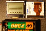
' Display pin 1 Vcc+ 3.2v

symbol SCLK = 0 'Display pin 2 to PICAXE out 0 (junction 6)
symbol SDA = 1 'Display pin 3 to PICAXE out 5 (junction 7)
symbol DC = 2 'Display pin 4 to PICAXE out 2  (junction 8)
symbol CS = 3 'Display pin 5 to PICAXE out 3  (junction 9)
' Display pin 6 gnd
' Display pin 7 Cap to Gnd 4.7uf electrolic

symbol RES = 4 'Display pin 8 to PICAXE out 6  (junction 10)
SYMBOL value   = b0
SYMBOL width   = b1
SYMBOL pointer = b2
SYMBOL X       = b3
SYMBOL Y       = b4
SYMBOL blinkstatus = b7
SYMBOL eeprom_addr = b5
SYMBOL GraphicData = b6
SYMBOL Loop1   = b10
SYMBOL loop3   = b12
SYMBOL SDA_PIN = outpin1 'outpin1 ************


Main:
        SETFREQ m8

        GOSUB InitLCD


	; This is the only section that is required to be changed
	; X = n is the x position on screen
	; Y = n is the y position on screen 
	; Change the following line to match the length of our display string, FOR pointer = 0 TO N
	;	N equals the length of the string
	; LookUp pointer,("Textstring"),value
	;	Textstring is the string to be dislayed
	;
	;
	; *****************************************************************
	; Display @ 0,0 Line 1
        X=0
        Y=0
        GOSUB GotoXY	
        FOR pointer = 0 TO 14
          LookUp pointer,("INIT COMPLETED"),value
          GOSUB ValueToLCD
        NEXT

	; Line 2, no change to X, display on line 2
        Y=1
        GOSUB GotoXY	
        FOR pointer = 0 TO 14
          LookUp pointer,("AWAITING SWITCH"),value
          GOSUB ValueToLCD
        NEXT

	; Clear line 1	
        Y=0
	  GOSUB GotoXY	
        FOR pointer = 0 TO 20
          LookUp pointer,("                       "),value
          GOSUB ValueToLCD
        NEXT

	; Some delay code
	pause 5000
	
	; Clear line 	
	Y=1
        GOSUB GotoXY	
        FOR pointer = 0 TO 22
          LookUp pointer,("                      "),value
          GOSUB ValueToLCD
        NEXT
	
	
huntingline:
	; Display message
       Y=0
       X=0
        GOSUB GotoXY	
        FOR pointer = 0 TO 14
          LookUp pointer,("HUNTING LINE    "),value
          GOSUB ValueToLCD
        NEXT

       Y=1
       X=0
        GOSUB GotoXY	
        FOR pointer = 0 TO 19
          LookUp pointer,("(((((((((())))))))))"),value
          GOSUB ValueToLCD
        NEXT
	

	;Main body


	; Removed code


	; end of main body

blinky:
	for pointer = 0 to 10
        gosub blink
        pause 1000
        sertxd (#pointer, 13, 10) 
      next
      gosub BlinkStar
      goto huntingline


fin:
        SETFREQ m4
        STOP
        END


Blink:
        GOSUB GoToHome
        low SDA
        high DC
        low CS
        X=79
        Y=5
        GOSUB GotoXY
        inc b7
        
        low SCLK
        if b7 = 1 then 
        	value = 0
        else
        	value = 255
        	b7 = 0
        end if
        GOSUB DataToLCD
        GOSUB DataToLCD
        GOSUB DataToLCD
        GOSUB DataToLCD
        GOSUB DataToLCD
        
	  high SCLK
Return

BlinkStar:
 
        X=79
        Y=5
        GOSUB GotoXY
	  FOR pointer = 0 TO 1
     		LookUp pointer,("*"),value
          	GOSUB ValueToLCD
        NEXT
Return

; version 1.01
;=====================================================================
; SUBROUTINES - Do not change. Refer to author
;---------------------------------------------------------------------
InitLCD:
        LOW SCLK
        LOW SDA
        LOW DC
        LOW CS
        LOW RES
        PAUSE 50
        HIGH RES
        HIGH CS

        Value=$21          ; $21 ==> H=1 and function set = chip active, horiz addressing & extended instruction set
        GOSUB CommandToLCD ; transmit To serial LCD module

        Value=$08          ; Set HV multiplier = x 2.                  For $09 = x3 set Vop at ~$C6 otherwise gives black screen
        GOSUB CommandToLCD ; transmit To serial LCD module

        Value=$F0          ; set Vop with (PRS = 0 Vlcd = 2.94V TO 6.75V)     If HV multiplier = $08 then use ~$C6
                                ; $E0=5.28V, $F0=6.3V, $FF = 6.72V  NOTE max allowed is 9V
        GOSUB CommandToLCD ; transmit To serial LCD module

        Value=$16          ; set bias: $16 ==> n=1 FOR mux rate 1:18 or 1:16 NOTE: n = 2 and n=5 DO NOT work
        GOSUB CommandToLCD ; transmit To serial LCD module

        Value=$06          ; set temperature coefficient = 2
        GOSUB CommandToLCD ; transmit To serial LCD module

        Value=$20          ; $20 ==> H=0 and function set = FOR basic instruction set
        GOSUB CommandToLCD ; transmit To serial LCD module

        Value=$0C          ; display config =  display non-inverted
        GOSUB CommandToLCD ; transmit To serial LCD module

        GOSUB GoToHome
        GOSUB ClearFast
        GOSUB GoToHome
        GOSUB Normal
 
        RETURN
;---------------------------------------------------- 
Invert:
        Value = 13        ; invert the display light chars on dark background
        GOSUB CommandToLCD
        RETURN
;---------------------------------------------------- 
Normal:
        Value = 12
        GOSUB CommandToLCD
        RETURN
;---------------------------------------------------- 
Blank:
        Value = 8
        GOSUB CommandToLCD
        RETURN
;----------------------------------------------------  
Allon:
        Value = 9
        GOSUB CommandToLCD
        RETURN
;---------------------------------------------------- 
GoToHome:
        X = 0
        Y = 0
GotoXY:
        Value = X + 128     ; 128 part = X address command 
        GOSUB CommandToLCD
        Value = Y + 64      ;  64 part = Y address command
        GOSUB CommandToLCD
        RETURN
;----------------------------------------------------


CommandToLCD:
       low DC 'Command mode
		DataMode1:
		low CS
		
		
		SDA_PIN = bit7
		PulsOut SCLK,1
		SDA_PIN = bit6
		PulsOut SCLK,1
		SDA_PIN = bit5
		PulsOut SCLK,1
		SDA_PIN = bit4
		PulsOut SCLK,1
		SDA_PIN = bit3
		PulsOut SCLK,1
		SDA_PIN = bit2
		PulsOut SCLK,1
		SDA_PIN = bit1
		PulsOut SCLK,1
		SDA_PIN = bit0
		PulsOut SCLK,1
		high CS
		Return
		DataToLCD:
		high DC 'Data mode
		DataMode2:
		low CS
		SDA_PIN = bit7
		PulsOut SCLK,1
		SDA_PIN = bit6
		PulsOut SCLK,1
		SDA_PIN = bit5
		PulsOut SCLK,1
		SDA_PIN = bit4
		PulsOut SCLK,1
		SDA_PIN = bit3
		PulsOut SCLK,1
		SDA_PIN = bit2
		PulsOut SCLK,1
		SDA_PIN = bit1
		PulsOut SCLK,1
		SDA_PIN = bit0
		PulsOut SCLK,1
		high CS
	return
;
;----------------------------------------------------
ValueToLCD:
        eeprom_addr=0
        IF Value>32 and Value <58 then
          eeprom_addr=Value-33
          eeprom_addr=eeprom_addr*5+130
        ELSEIF Value>64 and Value <91 then
          eeprom_addr=Value-65
          eeprom_addr=eeprom_addr*5
        ELSEIF Value=32 then
          Value = 0
          GOSUB DataToLCD
          GOSUB DataToLCD
          GOSUB DataToLCD
          GOSUB DataToLCD
        ENDIF
        IF Value=0 then
          RETURN
        ENDIF
        width = 4
        read eeprom_addr, Value
        IF value = 0 then ; found a narrow character
           width = 2
           inc eeprom_addr
        ENDIF
        FOR Loop1 = 0 TO width
          read eeprom_addr, Value
          inc eeprom_addr
          GOSUB DataToLCD
        NEXT Loop1
        value = 0
        GOSUB DataToLCD ; put a 1 bit space after each character for clarity
BaleOut: RETURN
;----------------------------------------------------

;----------------------------------------------------

	  	
ClearFast:
        Gosub Blank
        low SDA
        high DC
        low CS
        For Loop1 = 1 To 48
                For loop3 = 1 To 84
                        low SCLK
                        high SCLK
                Next loop3
        Next Loop1
        high CS
        Gosub Normal
Return
;----------------------------------------------------
eeprom 0,(0x7E, 0x11, 0x11, 0x11, 0x7E) ;A
eeprom (0x7F, 0x49, 0x49, 0x49, 0x36) ; B
eeprom (0x3E, 0x41, 0x41, 0x41, 0x22) ; C
eeprom (0x7F, 0x41, 0x41, 0x22, 0x1C) ; D
eeprom (0x7F, 0x49, 0x49, 0x49, 0x41) ; E
eeprom (0x7F, 0x09, 0x09, 0x09, 0x01) ; F
eeprom (0x3E, 0x41, 0x49, 0x49, 0x7A) ; G
eeprom (0x7F, 0x08, 0x08, 0x08, 0x7F) ; H
eeprom (0x00, 0x41, 0x7F, 0x41, 0x00) ; I
eeprom (0x20, 0x40, 0x41, 0x3F, 0x01) ; J
eeprom (0x7F, 0x08, 0x14, 0x22, 0x41) ; K
eeprom (0x7F, 0x40, 0x40, 0x40, 0x40) ; L
eeprom (0x7F, 0x02, 0x0C, 0x02, 0x7F) ; M
eeprom (0x7F, 0x04, 0x08, 0x10, 0x7F) ; N
eeprom (0x3E, 0x41, 0x41, 0x41, 0x3E) ; O
eeprom (0x7F, 0x09, 0x09, 0x09, 0x06) ; P
eeprom (0x3E, 0x41, 0x51, 0x21, 0x5E) ; Q
eeprom (0x7F, 0x09, 0x19, 0x29, 0x46) ; R
<snip>
 

Attachments

westaust55

Moderator
Graphic LCD 84x48 Nokia 511

I am jus looking at the code written for this. Its nice to look at how the programmer went about this, not to complex ,kinda elegant.
How does this work , the SDA_PIN = output1 line where the variable say for 'A" or 'B" is put into bit0....bit7. What happens if the bit is 1 or if the bit is 0.
Is the clock line saying ""read the bit"" this is the first time I have tried to look at this tycpe of comms.
thx for yr patience.

ps. the SDA and SDA_PIN, can both those assignments work on the same pin?
You might have done well/better to have posted to Anobium's thread rather than this thread but at the end of the day they are similar.


If you put a byte value (0 to 255) into variable b0, that corresponds to the bit variables bit0 to bit7.
The code puts each bit variable value one at a time starting with the most significant bit (bit7) through to the least significant bit (bit0)
Each bit is assigned in turn to the output pin 1 and then the clock is pulsed.
So whether the bit is a 1 or a 0 when the clock signal is pulsed, the LCD (or other receiving device) accepts that bit into its internal register.

With respect to the SDA and SDA_PIN, yes both can act upon the same pin
HIGH and LOW commands require a value and here SDA is assigned the value 1 for output pin 1
When assigning a level (high (=1) or low (=0) ) to a pin from variable the variable outpin1 has been used to indicate it is output pin 1.
 
Last edited:

shellakaa

Member
i think theres an ipad under the tree.

You might have done well/better to have posted to Anobium's thread rather than this thread but at the end of the day they are similar.
yeah i reazlised id maybe gone wrong thread. thx for your answer though.

westaust55 said:
Each bit is assigned in turn to the output pin 1 and then the clock is pulsed.
So whether the bit is a 1 or a 0 when the clock signal is pulsed, the LCD (or other receiving device) accepts that bit into its internal register.
That was the exact bit i was wanting to hear. pun unavoidable :) Ive really enjoyed just reading this code. I bought a nokia lcd with same driver chip and was all at sea with the datasheet. simply way above my pay grade though have been informed that it is a really poor datasheet . I see you are having no probs, getting off the beaten track with whatever screens you can salvage !! working out the values to create characters must be a big big job. is there any reason you and others stay with hex rather than decimal. thx again.

tHIS prompted me to read up on spi I2c -- hence the datasheet became some clearer with the diagrams but boy still murky.

Happy christmas.
 
Last edited:

westaust55

Moderator
Is there any reason you and others stay with hex rather than decimal. thx again.
While most folks through their respective educations are far more familiar with the decimal system that does not convert easily to bits and bytes.

While after many years (and many years ago until just 2.5 years ago) working with both decimal, hexadecimal and binary, I can do the byte wide conversions mentally lets just say that is not the norm for most folks.

however as mentioned when you consider that PIC microcontrollers (upon which PICAXE chips are based) typically do data manipulations in binary using just 1's and 0's. Also the IO ports and data locations are all 8 bits wide.

In binary, we can express these values in the format %11111111
That however takes a wile to type in each time.

binary to hexadecimal is a very easy conversion
you just group the first (most significant) four bits and then the second (least most significant) four bits

So
%10101101
becomes
%1010 1101
and in hexadecimal %10101 = $A and %1101 = $D
thus
%10101101 = $AD

When we want to change one bit for an IO port this is also easier to work out in binary or hex.

Lets say we want to make bit 4 of a port high

we can just OR the existing value with $00010000 (or $10) ; makes more sense than decimal 16 when working with bits

and if we want to turn off say bit 2

we can just AND the existing value with $00000100 (or $04) ; makes more sense than decimal 4 when working with bits


Have a look at the number conversion chart I previously created at post 20 here:
http://www.picaxeforum.co.uk/showthread.php?t=10893&page=2

Hopefully that will help you understand hexadecimal and binary a little better/easier
 
Last edited:

hippy

Ex-Staff (retired)
is there any reason you and others stay with hex rather than decimal.
It's really what's most 'instantly clear' in the particular circumstances. For a byte-wide 'pins' variable that's usually more easily thought of as a collection of 8-bits rather than as an 8-bit decimal number though both are the same.

"Let pins = %10000001" more clearly sets the msb and lsb bits of the output pins than 'Let pins = 129' does for most people and using a two-digit hex number, "Let pins = $81" can make it much easier for people to handle the 8-bits as two sets of 4-bits - to check that %10000001 is the same as $81 means having to count that there are six zeroes between the 1's which can be error prone in typing and in reading.

Do you read "w0 = %100000000000001" as "w0 = $8001" ? You shouldn't, because it isn't, though most would be tempted to. And how long does it take to count the zeroes, and to double-check your counting ? So is "w0 = %100000000000001" correct, is there a missing leading zero which would have made it clearer, or an accidentally dropped zero in the middle ? You have to do further checking to be sure.

Assuming it was intended as "w0 = $8001" it is clear that there is likely some significance in setting the msb and lsb through that assignment, with "w0 = 32769" it's not so immediately clear that there's any particular significance in the number used. Only when the decimal is converted to hexadecimal or binary does the significance become clearer so it's a favour for the reader in saving them the effort of finding the significance themselves.

Also, as a coder, when you come back to what you wrote some time later you are pretty much a reader yourself so you're saving yourself the effort of trying to work out what you had done and why.

This further extends to using named constants. "Let pins = $81" may be what's required to create a reset condition say, but rather than have code littered with those and having to remember "$81 is reset condition" it's easier to use -

Symbol RESET_CONDITION = $81

Let pins = RESET_CONDITION

Whether the reader understands why the reset condition is $81 becomes rather immaterial, it's up to them whether they wish to understand that and why, but they can likely see and understand what you are attempting to achieve simply through 'Let pins = RESET_CONDITION'. Again, you've greatly simplified things for everyone.
 

John West

Senior Member
This has been a most excellent and educational thread. Thank you for this clear, concise and thoroughly documented reverse engineering, adaptation and development effort.

It has been a pleasure to read something sane, thoughtful and intelligent on a Christmas Eve morning as I sip on a cup of eggnog and try to avoid reading all of the terrible national and international news.

The PICAXE is one of the few things in this world that makes some sense.
 

shellakaa

Member
i think so too

yes on phones ,data ,comms or number systems.,thx. I have used spi or i2c picaxe before to use an external 24lc16 eeprom. I had NO idea what I was doing, just magic picaxe commands :)

For myself I will stop becoming annoyed everytime i see hex, I dont believe i will be good at it but i see why others are and prefer as well as now lsb, msb has meaning. well i knew the meaning put with hex i see it actually begins to be practical.

Thats what id like to see in a picaxe manual, communication protocols to take the scared wetting your pants newbie to feeling like he can hang out with the older big kids :) You have just about done that for me in a couple of posts though i spent two days digesting SCLK, SDA, SDA_PIN bit0...bit7 from nokia code(WELL partially digesting, i was bit/hex intollerant)

Can you say even make up your own comms protocol between two picaxe chips and also do a timing diagram to go with it , or is that not a good idea im just thinking perhaps im typing not thinking?

Edit: I get carried away :)
 
Last edited:

westaust55

Moderator
I know I have the odd nuto idea/question. So one thing I am waiting on is an EEPROM board from http://www.futurlec.com.au/Mini_EEPROM.jsp

It could be handy storage and more SPI for me to look into.
That Futurlec EEPROM board is for i2c protocol EEPROMs
Price is okay though for a 4-chip board.

Rev Ed produce an 8-chip board as the AXE111 which is much the same and also uses the i2c protocol. Sold in Australia by several stores including:
http://www.microzed.com.au/index.php?main_page=product_info&cPath=15&products_id=79
and
http://www.altronics.com.au/index.asp?area=item&id=Z6155


Also to answer you question in the post 2 up from this, YES you could develop your own comms protocol by bit bashing. Would in the main only be useful for your own use but can be done.
See the example code in PICAXE manual 2 at the bottom of the pages for the SHIFTIN and SHIFTOUT command. If you have an X1 or X2 part and just want a different number of bits than 8, the SHIFTIN and SHIFTOUT command can also accomodate that.
 
Last edited:

shellakaa

Member
ill check out the microzed board

thanks, and i just thought making your own private comm protocol might help me but actually i dont see it having such a big advantage. It is going to be tricky at least a bit whatever spi or comms i need to use.

Ok so i didnt read properly the board i ordered is i2c, well thats good because i think it has been the easiest. It may well be quite involved but the picaxe commands are making it good.

I was reading shiftout in the manual last night and seemed that could have been used very successfully in the nokia code I have rather than what i think u refer to as bit banging going on there.

though the difference is negligible at a glance to me at least.
 

westaust55

Moderator
Great that you are on the right track so to speak.

It would be worth your starting a new thread for further quesitons, since this thread was for the use of the Siemens A55/C55 LCD graphics display
 
Last edited:

EricD

Member
Thought others may be interested in an Excel spreadsheet I whipped up to quickly get the required values for new fonts and other graphics to use on gLCD’s such as those from Nokia and Siemens mobiles as discussed todate in this thread.

It takes away the mental maths and lets you draw your creation pictorially and then just read off the hex values.

Obviously I cannot upload an excel spreadsheet (I guess Rev Ed wish to avoid any virus) and although there are ways to get around that limitation, I won’t promote that method here.

So for those interested, I have printed out a portion of the spreadsheet showing the formula and small lookup table and a second file with an example of a portion showing what it looks like when in use.

You should be able to cut the formula from the pdf file and paste them into a spreadsheet in the same manner to make your own graphic aid. Each spreadsheet cell formula is on a single line and I have shown 3 columns here. If you create one column, you can just drag the cells along to make what ever overall width you want.

Edit:
Should mention that I use a black coloured cell with with the value 1 in it. The coloured cell gives the visual effect and the number is necessary for the calculations to work. Just create one such cell then copy (Control-C) and past (Control-V) to put the markers where you want them.

Hi westaust55, I can't get the pdf files to work on Excel, if you still have them can you please email them to me if ok with you?

Thanks

EricD
 

westaust55

Moderator
A55 &amp; 3310 gLCD Font &amp; Graphic Creator Sheet

Hi westaust55, I can't get the pdf files to work on Excel, if you still have them can you please email them to me if ok with you?

Thanks

EricD
Hi Eric,

I have attached the Excel spreadsheet here with the file extension changed to .dsn

just change it to .xls and all should work.
Fonts page comes pre loaded with the Greek alphabet,
there is a second sheet with a larger display encoder page
plus a general worksheet.

Hope that your and others find it usedful
 

Attachments

wosscode

New Member
I toredown my 55 recently (not for any good reason) and was delighted to find a screen with a simple HW interface, then I find this thread on google and I can't wait to try driving this off my PIC. Thank you all for investigating this screen and it's interface so thoroughly.

This information will prove invaluable in my next project!

Cheers!
 

westaust55

Moderator
Welcome to the PICAXE forum.
It is good to know that the information provided in this thread is found to be useful by others.
 

tarts

New Member
Hi all,


Plugged in the A55 LCD module and with a minor tweak to the Nokia 3310 program from eclectic's thread and its voila !

a working 101 x 64 LCD display from the Siemens A55 mobile.


But the key point for now is that is is working :D :D
Could you please explain what were these minor tweaks you made!
I have a PIC 16f690 connected to LCD. In Proteus simulator it works with 3310 LCD, but C55 LCD is totally blanc.

EDIT: If anyone kows a working code in ASM language then please post it here, thanks!
 
Last edited:

westaust55

Moderator
Welcome to the PICAXE forum.

The "tweaks" related to voltage settings which are detailed in the BASIC program. Some settings may need adjusting to suit the supply voltage for best contrast (even a change of 0.3 volts on supply has an effect.

This forum is for the PICAXE range of micro controllers (not the native microchip PICs) which are predominantly programmed in BASIC. While a few members here do also dabble/work in assembler I doubt they have A55 LCD code available.
 
Last edited:

tarts

New Member
ok thanks.
So I can't see why my 3310 code doesn't work, since my supply voltage is 2,59V (a 3,3V regulator + diode).
Does your processor have built in serial interface that you're using(SPI)? My code has just some loops to write dserial data.
 
Top