5x7 Dot matrix display

cfarr

Member
I'm trying to control a 3 module 5 x7 dot matrix display with 3 cascading 74HC595 shift registers for the columns and a 4017 decade counter for the rows. The data for the text is stored in a contiguous table in an external 24c256 eeprom.
A PICAXE 20X2 will be used.

The steps for the software routines are as follows:

1) reset the 4017,
2) clock out the 15 bits representing the columns into the 595s,
3) Clock the 4017 on count one,
4) toggle the latch of 595,
5) Delay,
6) repeat from step 2 for the other rows,
7) when all 7 rows are done go to step 1.

I'm afraid the programming at step 2 is over my head considering the multiplexing factor.
I want to clock in the 15 bits of every row into the 595.

For example, the attached picture shows the data for displaying numbers 1,2, and 3.

clock bit 0 of each data value for row1 (5 bits per character)
clock bit 1 of each data value for row2 ...etc

From the forum, i know that SHIFTOUT command appears to be fastest but
I would apprciate any comments/feedback.
 

Attachments

lanternfish

Senior Member
Hi

I suggest you do a search of these forums (and google) to get a feel for what others have done.

I would try to use the outputs of the picaxe, via buffers, to directly drive the row anodes.

To drive the column cathodess, buffered by a uln2803(?), would use the 595's, as you have suggested.

And you could just initialise the first column bit and then clock the 595's; no SHIFTOUT required
 
Last edited:

lanternfish

Senior Member
I just had another thought:eek:

If you use B.0 to B.6 for the row outputs you can use sck (B.7) line to clock the 595's.

Andfor the 595's, as the data is clocked in on the low to high transition of the SH pin (11) and the previous data is shifted through to the storage register on the low to high transition of the ST pin (12), if these are tied together then you effectively latch the previous column bit while clocking in the new column bit. Confused :confused: - refer to the Philips datasheet for more info.

Hope this helps
 

cfarr

Member
Thank you Lanternfish and Westaust55. As far as I am concerned, I don't think I have any problems as regards the hardware. From Google searches, the method in my post is the most efficient and helps, if in the future, you opt for a moving display.

Westy, I have studied your posts and others and from there I opted to use the shiftout command using the SH pin and ST pin as Lanternfish pointed out. As regards the 4017, this is a decade counter that increments on every row count to source the current in the whole row, so that might not be a problem.

My problem arises, as how I am going to keep track of the bits to clock in the 595s, since you have to shift out bit0 of every column byte ,i.e 15 bits for row0 then activate the row by the 4017. Next shiftout bit1 of every column byte, i.e another 15 bits for row 1 and so on, until bit 6 of every column byte since bit 7 is not used as there are only 7 rows for each character. By the way 2 shift registers are enough to store 15 bits.

I hope that I have expressed my concerns. In the mean time, thanks in advance to you all, guys.
 

westaust55

Moderator
Does something like this help:

Code:
SYMBOL Digit1 =b4
SYMBOL Digit2 = b5
SYMBOL Digit3 = b6
SYMBOL Current = b7


[B]Send3chars:[/B]
FOR bits = 0 TO 6 ; once per column and  0 to 6 = 7 rows total
  Current = Digit1
  GOSUB shiftout_msb

  Current = Digit2
  GOSUB shiftout_msb
  Current = Digit3
  GOSUB shiftout_msb
  Digit1 = Digit1 * 2  ; shift each characters data left 1 bit
  Digit2 = Digit2 * 2
  Digit3 = Digit3 * 2
  GOSUB ClockRow ; here call your subroutine to advance the 4017 to the next row
NEXT bits
RETURN
;
[B]Shiftout_msb:[/B]
Mask = Current AND %10000000
LOW  DataPin
IF Mask = 0 THEN Skip_high
HIGH DataPin
Skip_high:
PULSOUT ClockPin, 1
RETURN
 
Last edited:

cfarr

Member
Thanks Westaus for your help. I have not tried your code yet, but I made modifications to suit my application, as far as I am concerned. I chaged the Digit1,Digit2, etc variables to ColumnData, representing the 5 column bytes for the character. The program runs in the editor with an example for displaying character 1. I still have to test the output as the led modules are not yet in hand, although I can try with discrete leds.

Code:
SYMBOL Column0 = b4
SYMBOL Column1 = b5
SYMBOL Column2 = b6
SYMBOL Column3 = b7
SYMBOL Column4 = b8

SYMBOL Current = b9
SYMBOL bits =b10
symbol mask=b11

symbol datapin=7
symbol clockpin=5


ColumnDataForChar1:
Column0=$0		'Hex data for column 0 )
Column1=$42		'Hex data for column 1 )
Column2=$7F		'Hex data for column 2 )to show char 1
Column3=$C0		'Hex data for column 3 )
Column4=$0		'Hex data for column 4 )


Send5columnData:

FOR bits = 0 TO 6 ; once per column and  0 to 6 = 7 rows total

  Current = Column0
  GOSUB shiftout_msb

  Current = Column1
  GOSUB shiftout_msb
  
  
  Current = Column2
  GOSUB shiftout_msb
  
  Current = Column3
  GOSUB shiftout_msb
  
  Current = Column4
  GOSUB shiftout_msb
  
  
  Column0 = Column0 * 2  ; shift each characters data left 1 bit
  Column1 = Column1 * 2
  Column2 = Column2 * 2
  Column3 = Column3 * 2
  Column4 = Column4 * 2
  
 ' GOSUB ClockRow ; here call your subroutine to advance the 4017 to the next row 
 'TEMPORARILY REMOVED
NEXT bits
'RETURN
;
end

Shiftout_msb:
Mask = Current AND %10000000
LOW  DataPin
IF Mask = 0 THEN Skip_high
HIGH DataPin
Skip_high:
PULSOUT ClockPin, 1
RETURN
 

moxhamj

New Member
Is 2) still the problem? If so, the good news is there is code etc here http://www.picaxeforum.co.uk/showthread.php?t=9116&highlight=hc595

The bad news is that I'm not sure this is going to be fast enough. I tried this with two 7 segment displays and there was a lot of flicker. Three 7x5 displays would be worse.

I've been pondering solutions to this. There are many that use high powered microprocessors, but I've been wondering about a way of using the piles of 2k and 8k ram chips I have lying around. Clock data into a ram chip using some 595s to do the data, address and rd/wr lines. It might need three 595s cascaded. Then when the ram chip is loaded, set it going very fast (1mhz?) to output.

I will ponder this some more...
 

cfarr

Member
I pondered into your code as well. But my application was a little different. For dot matrix displays, you have to set all the column data for each characters in one go, for example, for a display of 10 modules, you need 10 x 5 bytes. Then you have to extract bit0 of every variable and latch in the 595, and enable row 0. Extract bit1 of every variable, latch and enable row 1. Continue for the 7 rows.

In my application I am loading the character map into an external eeprom, read the data, buffer it and enable each row in turn. I am using a PICAXE 20X2 running at full speed. My intension is to increase the number of LED modules, hopefully making a moving display, but for now just getting the grip of it.

As regards multiplexing, I made a six digit 7 segment clock using PICAXE 40X2 running at 32MHz and reading time from a DS1307 clock, and displaying temperature and humidity every two seconds intervals. I managed to get 80 frames per second, most probably more with optimized software, as I am hardware oriented. It also works well with no flicker at 16MHz

For the moving display I have yet to build the hardware starting with maybe 8 modules. Then we’ll see. All suggestions are welcome, off course.
 

lanternfish

Senior Member
Hi again.

Catching up on this thread I feel you are making this harder than need be. and that I may not have been as clear with my description as I could have been.

As each module is 7 rows x 5 columns the following can apply:

1) As 1 byte is 8 bits the data for a column can by one byte with the display data held in bits 0 - 6. Bit 7 can be used as a flag bit or clock if desired.

2) To outupt, for example, a '1' in the first module you would output 00H then activate the 1st column (Col1). Then subsequently output 21H (Col2), FFH (Col3), 01H (Col4) and 00H (Col5).

This allows expansion for a large number of modules before display flickering will become a problem. Given the speed of X2 parts the display could be quite large.

If I read your post correctly you are wanting to address each led individually. But with data stored in eeprom you can provide all the necessary possible bit patterns quite easily. And lookup tables could tell you what value is stored in each column and so you only have to set/clear a bit in the table before outputting a byte to that column.

Am I making sense?

Cheers
 

westaust55

Moderator
Have you given consideration to the current capabilities of the IC's you are proposing.
Very similar words here to those I have just posted in another thread . . .

Many LED's have an absolute max rating of 20mA. If you look at most circuits, they include say a 330 Ohm or 470 Ohm resitor in series to limit the current to something like 11mA or 8mA.
In the past forum members here have reported that LED's can still be quite visible down to around 3 or 4mA.
So in that regard it will depend upon how far away and thus how bright you want your display to be.

With respect to IC's you need to learn to read the datasheets.
Datatsheets are your friend.

the ubiquitous 74HC595 shift register can handle up to +/- 35mA per output (that is sink or source)
but has a total chip Icc current limitation of +/-70mA so if driving 7 segments and a dp must limit the individual segemnt currents to around 8mA each.

The 4017 can typically source only 0.88 mA with a supply voltage of 5Vdc at 25 deg C per output
(This rises to 2.25mA at a supply volatge of 10V and 8.8mA at 15V)
Thus even driving just a single LED per output pin with any reasonable LED current for visibility you are overloading the 4017 chip on a 5Vdc supply.

When mutliplexing you can strech the boundaries by considering averaging of the current (but personnal I prefer a robust circuit).

Transistors for higher current drivers are therefore essential if you are wishing to handle more than the chip output capabilities.
 

cfarr

Member
Westaus, yes I am aware of the current considerations. However, this depends on the number of modules. The anode rows can be driven by a transistor or FET to source the current. On the other hand, for the columns a uln2003 can be connected to the 595s to sink the current. For the moment I am only pondering on the sowftware.

Lanternfish re:
2) To outupt, for example, a '1' in the first module you would output 00H then activate the
1st column (Col1). Then subsequently output 21H (Col2), FFH (Col3), 01H (Col4) and 00H (Col5).
But by this method you have to connect the columns to the counter and the data to the rows, am I right?
 

cfarr

Member
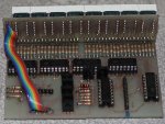
Still work in progress. Here is what I managed to achieve so far. For all the guys on here who helped me, thanks a lot. I am posting the code and some pictures. The schematic will follow.

Project: Dot matrix display

LED display board: Double sided PCB housing 8 5x7 dot matrix modules Kingbright TC07- 11EWA.
Drivers board: Double sided PCB with 5 x 74HC595 shift registers, 74HC138
multiplexer and row driver transistors.
CPU board: This is still on breadboard. It consists of a PICAXE 20X2, a DS1307 and
a 24LC512 eeprom. This board is to be built independently of the above
incase of future PICAXE upgrades so the led and drivers boards can be
reused.

I am no expert at working code, so any improvements, comments etc. are much appreciated. The software is commented to my best for ease of reference. Here is a brief description.
Mainly the display is represented by an array of 8x7 stored in the scratchpad area, which is immediately refreshed to show the changes. Characters are stored in an external eeprom. Data is fed to the columns via the shift registers and the display is refreshed at one go. This is done for each row. At present the display cycles through, displaying the word PICAXE, an 8 digit real time clock and the date and month. There is no sign of flicker and the refresh rate is 55Hz which is not bad. Till now, the display is static, no scrolling text yet. This is my next struggle to research and explore although I’d like to hear ideas, comments as how this could be implemented.

Again, thanks for all the valuable help.

Code:
; *******************************
; ***** Sample Header File  *****
; *******************************
;    Filename: 			DOT MATRIX DISPLAY
;    Date: 					21/04/2010			
;    File Version: 	
;    Written by: 		
;    Function:		
;    Last Revision:	
;    Target PICAXE:	
; ******************************* 
#PICAXE 20x2
SETFREQ M64

#No_Table
#No_Data

EEPROM 0, (" PICAXE ")	'7
'EEPROM 8, ("MONDAYTUESDAYWEDNESDAYTHURSDAYFRIDAYSATURDAYSUNDAY")' 57
EEPROM 58,("JANFEBMARAPRMAY")

Symbol CharPointer		=W4
Symbol TempByte1   		=B12
Symbol TempByte2			=B11
Symbol Get_    			=B13
Symbol DigitToDisplay=B14
Symbol Digit			=B15
Symbol RowNumber			=B16


Symbol Latch  	= B.3			'Columns Latch
Symbol SrClk 		= B.2			'Serial Data Clock 
Symbol SrData		= B.1			'Serial Data PIN		
Symbol SrClr		= C.7			'Serial Data Clear

Let DIRSC=%00000111 			'Make Port C OUTPUTS


Initialize:

	For b0= 0 to 56					'Initialize array by writing 1 to all locations in scratchpad
		Put b0,$FF						
	Next b0
	

	GOSUB Logo						'Display the word PICAXE
	

DisplayTime:	


Colon:									'Display the two colon separators for the time.


	GET_=0
	TempByte1	=5					'Update Digit 5
	
			
	FOR TempByte2=0 TO 1		'Repeat twice (for the two colons)
		CharPointer=406				'406= 'COLON' character pointer in eeprom
		
		DO											'
			PTR=Get_*8+TempByte1	'Calculate array index n*8  (this is for 8 characters)

			I2cslave %10100000, i2cslow, i2cword	'Read character from the 24C512
			Hi2cin CharPointer,(@ptr)							'and update scratchpad array.						
	
			Inc CharPointer
			Inc get_
		Loop until get_=7						

			TempByte1=2					' Now Update Digit 2				
			GET_=0	
	NEXT TempByte2	
	

'NOW READ THE TIME AND DISPLAY IT 	

	For TempByte2 = 1 to 50				' Duration of current time on display		
									'


		I2cslave %11010000, i2cslow_64, i2cbyte			'Initialize Clock
		Hi2cin 0,(b44,b45,b46)											'Read time 
		
		
		DigitToDisplay=b44 and $0F	'SECONDS UNITS
		Digit=7
		GOSUB UpdateDigit
		GOSUB RefreshDisplay

 		DigitToDisplay=b44/16				'SECONDS tens	
		Digit=6
		GOSUB UpdateDigit
		GOSUB RefreshDisplay

		DigitToDisplay=b45 and $0F	'MINUTES UNITS
		Digit=4	
		GOSUB UpdateDigit
		GOSUB RefreshDisplay
	
	
		DigitToDisplay=b45/16				'MINUTES TENS	
		Digit=3	
		GOSUB UpdateDigit
		GOSUB RefreshDisplay
	
		DigitToDisplay=b46 and $0F	'HOURS UNITS
		DIGIT=1	
		GOSUB UpdateDigit
		GOSUB RefreshDisplay

		DigitToDisplay=b46/16					'HOURS TENS
	
		IF DigitToDisplay=0 then		'BLANK LEADING ZERO
		DigitToDisplay=32						'ASCII SPACE dec number
		ENDIF
		
		Digit=0
		GOSUB UpdateDigit
		GOSUB RefreshDisplay
	
	Next TempByte2

	Gosub displaydate							'Display the date and month

	GOSUB Logo										'Display logo again
 
	GOTO DisplayTime							'Repeat


UpdateDigit:

	CharPointer=DigitToDisplay*7		'Fetch character in eeprom and get data
	GET_=0
		
	DO	
		PTR=Get_*8+Digit	'Calculate array index n*8  (this is for 8 characters)

		I2cslave %10100000, i2cslow, i2cword	
		hi2cin CharPointer,(@ptr)
	
		Inc CharPointer
		Inc get_
	Loop until get_=7
	
RETURN


DisplayDate:

		I2cslave %11010000, i2cslow_64, i2cbyte		
		Hi2cin 3,(b44,b45,b46)								'Read DAY,DATE,MONTH 


		DigitToDisplay=32						'ASCII dec value for  SPACE
		Digit=0
		GOSUB UpdateDigit


		DigitToDisplay=b45/16				;DAY TENS		
		Digit=1
		GOSUB UpdateDigit
		
	
		DigitToDisplay=b45 and $0F		'DAY UNITS
		Digit=2
		GOSUB UpdateDigit
	
		DigitToDisplay=32					'ASCII SPACE
		Digit=3
		GOSUB UpdateDigit


		Select Case b46						' Show month in letters. 'May' only up to now

		Case 5
		
			DIGIT=4
	FOR TempByte1 = 70 TO 72 		
		READ TempByte1,DigitToDisplay
 		GOSUB UpdateDigit 		
    INC DIGIT	   
	NEXT 
	
		Endselect	
	
		DigitToDisplay=32						'ASCII dec value for  SPACE
		Digit=7
		GOSUB UpdateDigit
	
	
	FOR TempByte2= 1 TO 200				'Duration of display showning date
		GOSUB RefreshDisplay
	NEXT TempByte2	

RETURN


Logo:														' Get data for the logo, in this case 'PICAXE'

		DIGIT=0
	FOR TempByte1 = 0 TO 7
		READ TempByte1,DigitToDisplay
 		GOSUB UpdateDigit 		
    INC DIGIT	   
	NEXT 

	FOR TempByte2= 0 TO 200			' Duration displaying logo
		GOSUB RefreshDisplay			' Refresh the entire display
	NEXT TempByte2

RETURN	

RefreshDisplay:								'

	RowNumber=0

	DO
		Ptr=RowNumber*8							'Goto scratchpad array 
		Shiftout SrClk,SrData,msbfirst,(@PTRINC/5,@PTRINC/5,@PTRINC/5,@PTRINC/5,@PTRINC/5,@PTRINC/5,@PTRINC/5,@PTR/5) 
		Pulsout latch,1
		Pinsc=RowNumber   
		Pause 4							'Delay
		Pinsc=%111					'Switch off rows
		Inc RowNumber
	Loop until RowNumber=7	
	
RETURN
 

Attachments

cfarr

Member
Still work in progress. Here is what I managed to achieve so far. For all the guys on here who helped me, thanks a lot.
I am posting the code and some pictures. The schematics will follow.

Project: Dot matrix display

LED display board: Double sided PCB housing 8 5x7 dot matrix modules Kingbright TC07-11EWA.

Drivers board: Double sided PCB with 5 x 74HC595 shift registers, 74HC138
multiplexer and row driver transistors.

CPU board: This is still on breadboard. It consists of a PICAXE 20X2, a DS1307 and
a 24LC512 eeprom. This board is to be built independently of the above
incase of future PICAXE upgrades so the LEDsand driver boards can be
re-used.

I am no expert at working code, so any improvements, comments etc. are much appreciated. The software is commented to my best
for ease of reference. Here is a brief description.
Mainly the display is represented by an array of 8x7 stored in the scratchpad area, which is immediately refreshed to show the changes.
Characters are stored in an external eeprom. Data is fed to the columns via the shift registers and the display is refreshed at one go.
This is done for each consecutive row. At present the display cycles through, displaying the word PICAXE, an 8 digit real time clock and the date and month.
There is no sign of flicker and the refresh rate is 55Hz which is not bad. Till now, the display is static, no scrolling text yet.
This is my next struggle to research and explore although I’d like to hear ideas, comments as how this could be implemented.

Again, thanks for all the valuable help.

Code:
; *******************************
; ***** Sample Header File  *****
; *******************************
;    Filename: 	DOT MATRIX DISPLAY
;    Date: 	21/04/2010			
;    File Version: 	
;    Written by: 		
;    Function:		
;    Last Revision:	
;    Target PICAXE:	
; ******************************* 
#PICAXE 20x2
SETFREQ M64

#No_Table
#No_Data

EEPROM 0, (" PICAXE ")	'7
'EEPROM 8, ("MONDAYTUESDAYWEDNESDAYTHURSDAYFRIDAYSATURDAYSUNDAY")' 57
EEPROM 58,("JANFEBMARAPRMAY")

Symbol CharPointer      =W4
Symbol TempByte1      =B12
Symbol TempByte2	      =B11
Symbol Get_    	      =B13
Symbol DigitToDisplay   =B14
Symbol Digit	      =B15
Symbol RowNumber      =B16

Symbol Latch  	= B.3			'Columns Latch
Symbol SrClk 	= B.2			'Serial Data Clock 
Symbol SrData	= B.1			'Serial Data PIN		
Symbol SrClr	= C.7			'Serial Data Clear

Let DIRSC=%00000111 			'Make Port C OUTPUTS


Initialize:

For b0= 0 to 56	'Initialize array by writing 1 to all locations in scratchpad
  Put b0,$FF						
Next b0

GOSUB Logo	'Display the word PICAXE
	
DisplayTime:	

Colon:			'Display the two colon separators for the time.
				
GET_=0
TempByte1=5	'Update Digit 5

FOR TempByte2=0 TO 1	'Repeat twice (for the two colons)
   CharPointer=406	'406= 'COLON' character pointer in eeprom

 DO									     
   PTR=Get_*8+TempByte1	    'Calculate array index n*8  (this is for 8 characters)
   I2cslave %10100000, i2cslow, i2cword	'Read character from the 24C512
   Hi2cin CharPointer,(@ptr)			'and update scratchpad array.	
   Inc CharPointer
   Inc get_
 Loop until get_=7						

   TempByte1=2		' Now Update Digit 2				
   GET_=0	
NEXT TempByte2	
	
'NOW READ THE TIME AND DISPLAY IT 	

For TempByte2 = 1 to 50		' Duration of current time on display		
   I2cslave %11010000, i2cslow_64, i2cbyte	'Initialize Clock
   Hi2cin 0,(b44,b45,b46)		'Read time 
		
   DigitToDisplay=b44 and $0F	'SECONDS UNITS
   Digit=7
   GOSUB UpdateDigit
   GOSUB RefreshDisplay

   DigitToDisplay=b44/16		'SECONDS TENS	
   Digit=6
   GOSUB UpdateDigit
   GOSUB RefreshDisplay

   DigitToDisplay=b45 and $0F	'MINUTES UNITS
   Digit=4	
   GOSUB UpdateDigit
   GOSUB RefreshDisplay
	
   DigitToDisplay=b45/16		'MINUTES TENS	
   Digit=3	
   GOSUB UpdateDigit
   GOSUB RefreshDisplay
	
   DigitToDisplay=b46 and $0F   	'HOURS UNITS
   DIGIT=1	
   GOSUB UpdateDigit
   GOSUB RefreshDisplay

   DigitToDisplay=b46/16		'HOURS TENS
     IF DigitToDisplay=0 then		'BLANK LEADING ZERO
       DigitToDisplay=32		'ASCII SPACE dec number
     ENDIF
   Digit=0
   GOSUB UpdateDigit
   GOSUB RefreshDisplay
Next TempByte2

GOSUB displaydate			'Now Display the date and month
GOSUB Logo			'Display logo again
 
GOTO DisplayTime			'Repeat

END

UpdateDigit:

   CharPointer=DigitToDisplay*7	'Fetch character in eeprom and get data
   GET_=0
DO	
   PTR=Get_*8+Digit	'Calculate array index n*8  (this is for 8 characters)
   I2cslave %10100000, i2cslow, i2cword	
   hi2cin CharPointer,(@ptr)   'Read from EEPROM
   Inc CharPointer
   Inc get_
Loop until get_=7
	
RETURN

DisplayDate:

   I2cslave %11010000, i2cslow_64, i2cbyte		
   Hi2cin 3,(b44,b45,b46)		'Read DAY,DATE,MONTH 
   DigitToDisplay=32		'ASCII dec value for  SPACE
   Digit=0
   GOSUB UpdateDigit

   DigitToDisplay=b45/16		;DAY TENS		
   Digit=1
   GOSUB UpdateDigit
		
   DigitToDisplay=b45 and $0F	'DAY UNITS
   Digit=2
   GOSUB UpdateDigit
   DigitToDisplay=32		'ASCII SPACE DEC VALUE
   Digit=3
   GOSUB UpdateDigit

 Select Case b46			' Show month in letters. 'May' only up to now!!
   Case 5
     DIGIT=4
FOR TempByte1 = 70 TO 72 	            'Read from Picaxe EEPROM 	
   READ TempByte1,DigitToDisplay
   GOSUB UpdateDigit 		
    INC DIGIT	   
NEXT 
Endselect	   
	
   DigitToDisplay=32		'ASCII dec value for  SPACE
   Digit=7
   GOSUB UpdateDigit
	
FOR TempByte2= 1 TO 200		'Duration of display showning date
   GOSUB RefreshDisplay
NEXT TempByte2	

RETURN


Logo:			' Get data for the logo, in this case 'PICAXE'

   DIGIT=0
     FOR TempByte1 = 0 TO 7
       READ TempByte1,DigitToDisplay
       GOSUB UpdateDigit 		
     INC DIGIT	   
   NEXT 

FOR TempByte2= 0 TO 200			' Duration displaying logo
   GOSUB RefreshDisplay			' Refresh the entire display
NEXT TempByte2

RETURN	

RefreshDisplay:								'

    RowNumber=0

DO
     Ptr=RowNumber*8	'Goto scratchpad array 
     Shiftout SrClk,SrData,msbfirst,(@PTRINC/5,@PTRINC/5,@PTRINC/5,@PTRINC/5,@PTRINC/5,@PTRINC/5,@PTRINC/5,@PTR/5) 
     Pulsout latch,1
     Pinsc=RowNumber   
     Pause 4			'Delay
     Pinsc=%111			'Switch off rows
     Inc RowNumber
Loop until RowNumber=7	
	
RETURN
 

westaust55

Moderator
Excuse me for the double posting. Ignore the last post.
When you are logged in, you will see an EDIT button in the bottom right of the screen.
Click on that and you can go back in and edit a post, manage attachments and even delete a double post.

To access some of the features you will need to click on the GO ADVANCE button (also lower right of screen) that appears when you go back into a post with the EDIT button


AND

congratulations on getting your "Jumbo" display working. The hardware looks very neat
 
Last edited:

cfarr

Member
Thank you Westaust55 for the remarks and compliments. As regards the scrolling text feature, do have any suggestions?
 

westaust55

Moderator
Thank you Westaust55 for the remarks and compliments. As regards the scrolling text feature, do have any suggestions?
Yes always possible to scroll but a little in retrospect/hindsight, this can be far easier to do if the display is column rather than row orientated.

With either row or column orientated driver, you should use a buffer than has the data for the required display. Of course this is easiest if this buffer can hold the entire message and then use pointers which operate akin to a small window into the entire data buffer.

If the display is column driven and the buffer has the data on a column basis then a scrolling display should be easy.
Can you upload your actual schematic diagram of the project to get a clearer picture of possibilities to make comment – rather than interpret from the code.
 

cfarr

Member
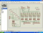
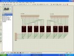
I am attaching the schematics for the driver and led boards. The CPU shematic is not drawn yet, but I don't think that it will be a problem to interpret how the circuit works. The CPU board just connects to J2 on the driver board, pins 1,2, and 3 to the CPU PortC to drive the rows and pins 4-8 to drive the shift registers. The remaining two pins are the supply.
 

Attachments

westaust55

Moderator
Okay, as by my reading, you have set up to store data for characters on a row by row basis as opposed to a colum by colum basis, here is some PICAXE pseudo code on how to create a leftward scrolling display.

Assumes:
1. That EEPROM data is saved as the 5 most significant bits for character data and 3 least significant bits are zero.
2. Keep the first 8 bytes (0 to 7) of scratchpad as a temporary buffer to hold data
3. The character buffer used to display the message starts at byte 8 of the scratchpad

Action starts here:

Copy the desired data for the entire text string into the scratchpad buffer with first character using the first 8 bytes. As 1 byte per character row. Have (at least) one space character on the end of the buffer so as message rolls around there is a gap.

DO
GOSUB Display the first 8 characters on the 8 char 5x7 LED display modules
FOR char = 0 TO length_of_textbuffer - 1
For row = 0 to 7
CurrentScratchpadAddr = char * 8+row + 8
NextCharAddr = CurrentScratchpadAddr + 8
GET CurrentScratchpadAddr, CurrentChar
NextPixel = CurrentChar AND $80 / $10
IF char = 0 THEN
PUT row, NextPixel ; save left most leading edge
ENDIF
CurrentChar = CurrentChar * 2 ; shift data left 1 “pixel”

IF char < length_of_textbuffer-1 THEN
Get NextCharAddr, NextPixel
NextPixel = NextPixel AND $80 / $10
ELSE
GET row, NextPixel ; if it is the last character, then roll in the column of pixels from left hand side
ENDIF
CurrentChar = CurrentChar OR NextPixel
PUT CurrentScratchpadAddr, CurrentChar
NEXT row
LOOP
 

cfarr

Member
Well thank you very much for the input. It&#8217;s nice to find people like yourself with great knowledge and willing to help.
I will study and try to understand your pseudo code and then try to implement it in my code. In order to keep things simple, I have modified my code to just display the word PICAXE. I am going to give it a try and see if I succeed. Thanks again for the info and I will post back with the results.

Code:
#PICAXE 20x2

 SETFREQ M64

#No_Table
#No_Data

EEPROM 0, (" PICAXE ")

Symbol CharPointer    =W4
Symbol TempByte1    =B12
Symbol TempByte2	    =B11
Symbol Get_    	    =B13
Symbol DigitToDisplay =B14
Symbol Digit	    =B15
Symbol RowNumber    =B16

Symbol Latch  	= B.3			'Columns Latch
Symbol SrClk 	= B.2			'Serial Data Clock 
Symbol SrData	= B.1			'Serial Data PIN		
Symbol SrClr	= C.7			'Serial Data Clear

Let DIRSC=%00000111 			'Make Port C OUTPUTS

Initialize:

For b0= 0 to 56	'Initialize array by writing 1 to all locations in scratchpad
  Put b0,$FF	'Write 1 to scrachpad to switch off all leds.
Next b0
	 
ReadDataToBeDisplayed:			' 

DIGIT=0

FOR TempByte1 = 0 TO 7		'Read the word PICAXE from EEPROM 0
   READ TempByte1,DigitToDisplay
   GOSUB UpdateDigitInScratchPad 	'Store data bytes in scratchpad array		
   INC DIGIT	   
NEXT TempByte1 

RefreshDisplay:	

RowNumber=0
DO
   Ptr=RowNumber*8     ' Goto scratchpad array 
   Shiftout SrClk,SrData,msbfirst  (@PTRINC/5,@PTRINC/5,@PTRINC/5,@PTRINC/5,@PTRINC/5,@PTRINC/5,@PTRINC/5,@PTR/5) 
   Pulsout latch,1
   Pinsc=RowNumber   
   Pause 4		'Delay
   Pinsc=%111	'Switch off rows
   Inc RowNumber
Loop until RowNumber=7	
	
Goto RefreshDisplay

END

 UpdateDigitInScratchPad:

CharPointer=DigitToDisplay*7     'Fetch character in ext eeprom and get data
GET_=0
DO	
   PTR=Get_*8+Digit	'Calculate array index   (this is for 8 characters)
   I2cslave %10100000, i2cslow, i2cword	
   hi2cin CharPointer,(@ptr)
   Inc CharPointer
   Inc get_
Loop until get_=7
	
RETURN

#REM

This is the scracthpad array to store the data for digits before they are 
displayed.  This is done in the software routine 'UpdateDigitInScratchpad'.


'SCRATCHPAD ARRAY

 LED7	LED6	LED5	 LED4 LED3	LED2	LED1	LED0
----- ----- ----- ----- ----- ----- ----- -----
 7	6	5	4	3	2	1	0
 15	14	13	12	11	10	9	8
 23	22	21	20	19	18	17	16
 31	30	29	28	27	26	25	24
 39	38	37	36	35	34	33	32
 47	46	45	44	43	42	41	40
 55	54	53	52	51	50	49	48

	P	I	 C           A            X          E
 
Last edited:

cfarr

Member
It is very important to use the sub procedure named ‘RefreshDisplay’ in my code in post #22 or something similar to it. The columns must be updated in one whole shot for each consecutive row, otherwise the display won’t look good, the leds which are supposed to be off will be dimly lit. I managed to get this perfect but only on a static display.

All the data to be displayed, must first be created in a sort of ghost display in the scratchpad. This array will be the memory ghost display. Whichever bits are required to turn on/off must be set in this array. The 40 bits must be updated for every consecutive row, hence
Code:
Shiftout SrClk,SrData,msbfirst,(@PTRINC/5,@PTRINC/5,@PTRINC/5,@PTRINC/5,@PTRINC/5,@PTRINC/5,@PTRINC/5,@PTRINC/5)
My apologies if I have not explained myself clearly.
 

Attachments

Top