pic to picaxe serial communication

steiner

New Member
I have a project that was originally designed for a 08m to communicate with a 28x1. It works well. I am now trying to substitute a pic 12F683 in place of the 08m picaxe. I am having problems with the serial communication. Does anyone know of any specific problems when doing this?

I am using serout with the 12F683 and serin with the 28x1. Both are operating at the same frequency and baud rate.

I have put a scope on the output of the 08m and the 12F683. The signals look different so I think this is the problem. However, I am really not sure what to do to change the output of the 12F683.
 

Andrew Cowan

Senior Member
What code are you running on each (the 08M and the raw 12F683)?

Can you take a photo of the scope signals?

Welcome to the forum!

Andrew
 

hippy

Ex-Staff (retired)
I am using serout with the 12F683
How are you doing that ? The most common problems with bit-banged code written in assembler or a high level language are -

Getting the bit timing wrong ( baud rate )
Sending the wrong number of bits
Sending data msb first
Getting the signal polarity inverted
Getting start and/or stop bit polarity wrong
Not using data bit polarity inverted compared to idle polarity
Not disabling interrupts during transmission
Watchdog timing out during transmission

If using MPLAB you can single step the code and see exactly what it is doing.
 

steiner

New Member
The attached file "0478x" is from the 12F683 and "0481x" is from the 08m which does work. The 0481x signal is repeating every 200ms and the 0478x signal is repeating about every 140ms.

I am using the picaxe program editor to write the code for the 08m and I am using PicBasic Pro to write the code for the 12F683. I have never written standard assembly code for the pic series. PicBasic Pro and picaxe commands are very similar so it was fairly easy to move from one to the other.

I was under the impression that both of these transmitted data at 8, none and one.

I am sending the data inverted because I have optical isolation between the board that contains the 8 pin micro and the board that contains the 28x1 micro.

Thanks for the help
 

Attachments

retepsnikrep

Senior Member
Rick. I presume you are sending a simple single test byte of known (value?) using both systems so we can see the difference in waveform?

Can you capture the waveform for a complete byte for each setup? Lets us know the test value as well and we can use that to look at the waveform.

Remember the Serial output for the original project is now (T=True Idle High) for the Slave output not (N=Inverted Idle Low). Check the latest Slave software.

Please post your code assembler/pic basic pro and the Picaxe Slave code.

Peter
 
Last edited:

slurp

Senior Member
When I tried something similar I found my self tweaking the code for High and Low bits with a few NOPs to ensure that the signal gave the same length to each bit (high or low).

The 'scope was most helpful!

best regards,
colin
 

hippy

Ex-Staff (retired)
If using library code or in-built commands the timing and formatting should be correct so the most likely issue, if everything else is correct, is the signal polarity. That's easy enough to test simply by specifying the opposite of what you have and trying it.
 

steiner

New Member
Peter,

Yes, I have both programs sending the same constant value of 200. I'm still running the older software that sends the data inverted. Both of the signals on the scope are displaying inverted data.

This is my first time looking at serial data on a scope. I didn't think this looked like a complete byte. However, the next data is 200 msec later. Should the individual bits be seperated by 200msec? I expected to see a start bit followed by the 8 data bits (11001000) and then one stop bit.

I will try sending the data from the 12F683 as true instead of inverted just because it is so easy to do.

What is the best way to attach the code? When I tried cut and paste it wraped the comments making it difficult to read.
 

steiner

New Member
OK, I tried the 12F683 at 2400 baud both true and inverted. I also tried it at 1200 baud both true and inverted. None of these worked.

Someone please check my thinking to make sure I understand serial communication. If we are sending the value of 200 that should be 11001000 in binary form. It is my understanding that 2400 baud which is 416.6 usec is the amount of time necessary to send each bit. If we have 8 bits that would equal about 3.33 msec. I don't know how long the start and stop bit is suppose to be. My scope is showing a clear 1 msec pulse on each end of the data. I was wondering if these are the start and stop bits. Is my logic correct?
 

retepsnikrep

Senior Member
If you look at the structure of the Picaxe serial output comms on the scope you should be able to work out which are start/stop bits etc in realtion to your value 200.

The waveforms you posted don't look very square have you got adequate pull up/downs on the optos etc

Are you sure about cpu speed and baud rate being correct.

Are you sure your constant is being treated as dec/hex etc.

I suggest post code to your own webspace and then link it here if you can't make the code thing work correctly here.
 

hippy

Ex-Staff (retired)
On your scope sending a byte of value 200 ($C8) you should see ...

Code:
__________----_--___________ for N2400

----------____-__----------- for T2400
          S01234567P
The N2400 and T2400 is with respect to the PICAXE, your software may use different terminology or conventions.

Each bit time should be 416.7us, the start and stop bits have the same timing. 8 data plus start and stop = 4167us per byte.

For checking timing send a byte of value 85 ($55) ...

Code:
__________-_-_-_-_-_________ for N2400

----------_-_-_-_-_--------- for T2400
          S01234567P
For bit ordering and timing send 53 ($35) ...

Code:
__________-_-_-__--_________ for N2400

----------_-_-_--__--------- for T2400
          S01234567P
 

hippy

Ex-Staff (retired)
What is the best way to attach the code? When I tried cut and paste it wraped the comments making it difficult to read.
You can either embed it in [code]...[/code] tags and put it inline or click on Quote when replying and there's an "attachment manager" lower down the page which allows code to be uploaded.

While people may be able to offer some advice on your code, you may be better off asking on a PIC Basic Pro forum where people will likely have experience of using it and be more aware of any nuances involved.
 

steiner

New Member
Well, here is the latest. This has me stumped. I did what hippy said and changed the value that was being sent to 85 (great idea by the way). I then put the scope on when the picaxe was sending the data (which works by the way) and recorded the file "picaxe". Since I knew this worked I figured that was my target to achieve using the pic chip. Well I tried several things one of which was changing the speed of the oscillator to 4 Mhz on the pic which was originally 8 Mhz (The speed of the recieving picaxe chip is running at 8 Mhz). This got the signal very close and then I simply added a 1msec pause and it matched perfectly (see "pic 4Mhz"). The only issue is I am still getting a communication error (timeout) message when the pic chip is sending the data.

Any ideas???
 

Attachments

retepsnikrep

Senior Member
Rick

The waveforms are horrible in the pics, pull up's or pull downs's?

They should be very square pulses. Not those slopping rising edges.

Are you actually trying this with opto isolation?

Might be an idea to connect the pic directly to the 28X1 for testing, get that working then add the opto isolation layer.

Is the 28X1 set for the correct number of slaves?

The timing looks slightly off at the end in the pic version.
 

steiner

New Member
Peter,

I know, I thought the wave forms didn't look very good. These readings are taken on the master side of the opto which uses a pull down. I think I need to reduce the value of R8 on the master.

That being said, the system works when using the picaxe on the slave. I see the small difference you are talking about but it looks like it actually starts in the first negative pulse that is a little more than 1 msec. Maybe I can reduce the small delay I inserted.
 

hippy

Ex-Staff (retired)
This got the signal very close and then I simply added a 1msec pause and it matched perfectly (see "pic 4Mhz").
I don't think it does. For sending 85 ($55) ...

Code:
------__-_-_-_-_-_------     is what is seen on the scope

-------_-_-_-_-_--------     is what should be seen
       S01234567P
Even if we ignore the fact that the start bit is twice as long as it should be, you have 5 positive going pulses during transmission, there should only be 4. That is probably a parity bit being generated.

Have you checked the PICAXE does receive 85 ($55); I'd have expected it to receive 170 ($AA) at best.

I don't understand how the PIC can be getting a "timeout" when sending, what that may mean, and how you are determining that is happening ?
 

hippy

Ex-Staff (retired)
Here is the code for the pic.
Get rid of all the unnecessary clutter, don't run within interrupts nor enable them. Simply focus on getting SEROUT to work. Try ...

High MasterBus
VData = 85
TestLoop:
Pause 1000
Serout MasterBus, N1200, [VData]
Goto TestLoop
 

hippy

Ex-Staff (retired)
Woke up this morning and it was suddenly obvious what your mistake is ....

Code:
------__-_-_-_-_-_------     is what is seen on the scope

________-_-_-_-_-_______     is what should be seen
        S01234567P
The HIGH you are forcing after the byte is sent explains the not quite right stop bit timing in your trace and then you have to set the line LOW because you set it HIGH after the last byte was sent.

Considering this all worked with a PICAXE, what is the rationale for using a PICmicro instead ?
 

steiner

New Member
hippy,

I stripped everything out like you suggested but I still get the same results. I then remed out the low and high on either side of the serout and I then get what your art work shows. However, it still doesn't work.

Peter, who has had a few inputs on this thread is actually the author of this code written for picaxe. I wanted to try to port the code over to a pic because that is what I am more familiar with (although it doesn't show here). They are also a little cheaper and available at mouser and digikey which is where I purchase most of my electronic components.

For the amount of effort I have put into this, I am about ready to give in and just use the picaxe. I must admit though I have learned a great deal about serial communication. In the past it always just worked and it seemed simple.

Using the scope and knowing that the picaxe chip works, I thought I would just keep tweaking the pic code until the display on the scope matched the picaxe display. Is this thinking correct?

To get the pic chip to be very close, I had to run it at 4Mhz, use 2400 baud, and insert an intial delay of 1100 usec. Will this work even though the receiving chip is running at 8 Mhz or does it simply not care as long as the timing is correct?

Last question....how close does the timing need to be?

Thanks for everyone's help...
 

Attachments

retepsnikrep

Senior Member
Rick

The current working at 4800 baud picaxe code I use is.

Master
Code:
symbol Baud4800    = N2400 	;Max baud rate 4800 at 8mhz (T=True Idle High)(N=Inverted Idle Low)
serin [TimeOut,DataError],MasterBus,Baud4800,@ptrinc ;Rxd Data on Master Bus into Scratchpad Ram and inc pointer
The Master uses Inverted mode (Idle Low) to receive.

Slave
Code:
symbol Baud4800    = T2400      ;Baud rate 4800 at 8mhz (T=True Idle High)(N=Inverted Idle Low)
high MasterBus			;Turn off MasterBus Optocoupler (Reqd due to sink driven) This line is at begining of program
serout MasterBus,Baud4800,(VData)	;Send VData (b0) to Master at Baud4800
The Slave uses True mode (Idle High) to transmit due to the sink driven opto isolation. I only set the Masterbus line high once now at the begining of program to turn off the opto led so it is ready for the first True serial output when it occurs. After a byte has been sent it idles high (opto off) until ready for the next byte.

If you can match both displays then it should work. The waveforms look a lot better now. Keep at it you are nearly there!!!
 
Last edited:

hippy

Ex-Staff (retired)
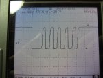
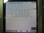
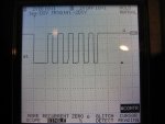
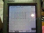
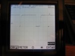
From the PICAXE screen shot it appears this is more than simple 'send a byte' stuff, or there's some misunderstanding of PICAXE baud rate polarity. The polarity should be chosen to match what is being driven, in this case it seems to be an opto and it wants an active high idle. What you appear to have from looking at the trace is a PICAXE sending using Nxxxx with some HIGH and LOW kludged in to get the idle high. You shouldn't need to do that, a Txxxx baud rate will do all that for you. It will require a single HIGH at reset, a HIGH before sending is not required, but adding it shouldn't do any harm as it simply sets the level high as it would already be using Txxxx.

On the receive side, it's a case of circuit analysis or observation to determine if the serial is idle low or idle high, use Nxxxxfor idle low, Txxxx for idle high.

It would clarify things if you could post your transmit and receive circuits along with their respective codes.

Best serial comms practice is to configure the line then leave the line alone, apart from using SEROUT to transmit data. For an opto between output pin and +V you ideally want to transmit with Txxxx, between pin and 0V you ideally want Nxxxx; this will minimise the amount of time the opto LED is on and reduce current.

I suspect that some nuance of PICAXE timing allowed what you had with two PICAXE to work, you have just been lucky with the data values you have been sending, or you haven't observed any consequences from incorrect data being received.

My approach would be to go back to two PICAXE with simple test programs, and adjust baud rate Nxxxx/Txxxx to match the hardware on transmit and on receiver to make it work.

' Transmitter
Symbol TX_PIN = ?
Symbol TX_BAUD = T2400
b1 = TX_BAUD : If b1 < 4 Then : High TX_PIN : End If
Do
Pause 500
SerOut TX_PIN, TX_BAUD, (b0)
b0 = b0 + 1
Loop

' Receiver
Symbol RX_PIN = ?
Symbol RX_BAUD = N2400
SerIn RX_PIN, RX_BAUD, b0
Do
b1 = b0 + 1
SerIn RX_PIN, RX_BAUD, b0
SerTxd( #b0," ")
If b1 <> b0 Then : SerTxd( "FAILED " ) : End If
Loop

Get that working, add SETFREQ M8 to each, test again, then replicate the transmitter code in the non-PICAXE.

Serial timing has to be within +/-6% overall.
 

steiner

New Member
hippy,

The slave circuit is located at http://www.solarvan.co.uk/bms/DigitalSlave080908.jpg. The master is located at http://www.solarvan.co.uk/bms/Master231008V2.jpg. I have attached both the slave and master software.

The serial communication is initiated when the master send a signal to the U3 optocoupler. This is turn tells the picaxe to transmit the serial data via the U2 optocoupler. It is being sink driven by P2 on the picaxe. I belive this is why the code is transmitted as inverted. This data is then transmitted out the J3 connector to the J13 connector on the master. This line is normally pulled low by R8 which was changed to a 1K resistor to clean up the signal. Once completed, the slave sends a signal to the next slave via the J4 connector to transmit its data.

The software for the pic chip has been stripped down to:

Loop1:
if slavebusIn = 1 then Loop1 'Wait until pin 4 is low
VData=85
low MasterBus 'Reqd due to sink driven
PAUSEUS 1100
serout MasterBus,T2400,[VData] 'Send VData to Master high MasterBus 'Reqd due to sink driven
GOTO Loop1
 

Attachments

Top