Wood Clock (yes it is a Picaxe project)

alpacaman

Member
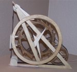
It's a wooden clock with 2 gears. One for the minutes had and one for the hours. The gears are turned by levers wich are attache to a belt around some pulleys. The main pulley is turned by a rc servo.

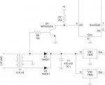
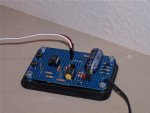
A picaxe 08M converts the 60hz coming from the wall to a one minute pulse. Another 08M receives the one minute pulse and controls the servo.

I tried using a single 08M but because of the pauses required to let the servo travel a minute turned into 73 seconds.
 

Attachments

Dippy

Moderator
I was , (by using a semi-rhetorical question), trying to suggest a note of caution if you were going to post details if there was a DIY mains voltage connection aspect.

It's a nice,attractive job you've done and therefore may have excited total novices to attach their PICAXEs to the mains voltage.
As you know there is a spectrum of experience/knowledge in the Forum.
Ranging from "very clever" down to "none and admits it", with a small contingent of "none, but I know more than anyone else".
Take the latter, stir in mains voltage and this could equal a painful result.
Maybe I'm being a bit nanny-ish ;)
 

Mycroft2152

Senior Member
It's a nice,attractive job you've done and therefore may have excited total novices to attach their PICAXEs to the mains voltage.
As you know there is a spectrum of experience/knowledge in the Forum.
Ranging from "very clever" down to "none and admits it", with a small contingent of "none, but I know more than anyone else".
Take the latter, stir in mains voltage and this could equal a painful result.
Dippy,

The DARWIN Award is always available.

Myc
 

alpacaman

Member
I was , (by using a semi-rhetorical question), trying to suggest a note of caution if you were going to post details if there was a DIY mains voltage connection aspect.

It's a nice,attractive job you've done and therefore may have excited total novices to attach their PICAXEs to the mains voltage.
As you know there is a spectrum of experience/knowledge in the Forum.
Ranging from "very clever" down to "none and admits it", with a small contingent of "none, but I know more than anyone else".
Take the latter, stir in mains voltage and this could equal a painful result.
Maybe I'm being a bit nanny-ish ;)
Point well taken. Yes the timing is coming from mains but it is well conditioned. You CAN'T just take the 50/60 hz from the wall and attach it to the input of the Picaxe. It's just like powering your Picaxe project from the mains, you will blow it up is it isn't conditioned (voltage regulator) properly. Of course I'm not using a voltage regulator in the timing circuit.

If you're considering a project where you'd like to use the mains as a timing source, and you're not sure how to do, please feel free to drop me a note.
 

AndyGadget

Senior Member
Synchronisation to mains frequency.

Hi Alpacaman - Great looking clock.
I'm about to start a timer project where I need a simple clock function but don't need full RTC facilities and looking to synch to the (50Hz) mains.
Looks like you're powering your project straight from a transformer with the regulation on-board. For your synch signal, are you taking AC from the bridge input then squaring and level shifting?
 

jc173

Member
I'm going to say something really quite dumb here....

could you not get the picaxe to move the servo, pause for 60 seconds (pause 60000) and then move the servo again, then if it gets to 60 minutes it moves the other hand (another motor) ...

or am i being silly here...
 

slimplynth

Senior Member
The time error using just a picaxe is too much to use it as an accurate clock. It's in the manual somewhere - think it's ±50% depending on the environment/temperature it's operating in
 

alpacaman

Member
Hi Alpacaman - Great looking clock.
I'm about to start a timer project where I need a simple clock function but don't need full RTC facilities and looking to synch to the (50Hz) mains.
Looks like you're powering your project straight from a transformer with the regulation on-board. For your synch signal, are you taking AC from the bridge input then squaring and level shifting?
The picture shows how I'm doing it. Of course there is always the possibility that the transistor will short out which might take out the Picaxe. You could use an opto-isolator. I use an interrupt routine to detect the pulse.
 

Attachments

alpacaman

Member
I'm going to say something really quite dumb here....

could you not get the picaxe to move the servo, pause for 60 seconds (pause 60000) and then move the servo again, then if it gets to 60 minutes it moves the other hand (another motor) ...

or am i being silly here...
About the timing slimplynth said it exactly. I did play around with using the pause command on another clock project and wasn't happy with it at all. Some may say that the timing from mains isn't all that accurate either. From what I read, many years ago, the mains timing over a short time span isn't too accurate but over a long time span it's very accurate.

I could have used 2 motors instead of one but that would have added the cost of another motor and increased the overall size of the clock to fit it in. Plus I just liked the overall design.
 

hippy

Ex-Staff (retired)
The time error using just a picaxe is too much to use it as an accurate clock. It's in the manual somewhere - think it's ±50% depending on the environment/temperature it's operating in
Temperature and operating voltage will affect the accuracy of the internal oscillator but on most PICAXE's it is better than +/-5% at room temperature and can be as accurate as +/-1% under ideal conditions.

Even a 1% error gives poor 'real world clock' accuracy; +/-15 minutes per day.
 

slimplynth

Senior Member
Assume makes an Ass out of you an me

I'd just assumed that the pause function used the same internal timers as sleep, nap, doze which the manual states are subject to -50 +100% tolernaces based on operating conditions.
 

AndyGadget

Senior Member
The picture shows how I'm doing it. I use an interrupt routine to detect the pulse.
That looks good to me, but just a thought - A bit more protection would be to put in a diode, cathode to the base of the transistor, anode to GND. This will stop the base going more than 0.7V negative on the down cycles.

I remember from way back that the total number of cycles in a day will be consistent - They 'catch up' overnight. Quite an achievement when you consider the size of a national grid.
 
Last edited:

BeanieBots

Moderator
If you look at it RIGHT NOW, you will see it right down at 49.9Hz in the UK.
Must be lots of people cooking lunch on electric.
I'd expect that to pop up to 50.1Hz for while shortly after the lunch break.
 
I would like to understand how to condition the wall socket frequency into a PICAXE input....thanks in advance.
Regards
Der Fisherman
 

goingsolo

Member
I would like to understand how to condition the wall socket frequency into a PICAXE input....thanks in advance.
Regards
Der Fisherman
In an earlier post alpacaman gave the schematic he's using to do this. He's taking the low AC voltage from the transformer and driving the base of a transistor. When the voltage reaches a certain level it turns on the transistor. The collector of the transistor then goes low. When the voltage on the base of the transistor drops below the transistors turn on voltage the transistor turn off again. The pull-up resistor on the collector pulls the voltage on the picaxe's input pin high again. This effectively gives you a 50/60hz, depending where you live, square wave.
 

BCJKiwi

Senior Member
There is the Microchip Application Note (as previously suggested by WestAus55) and available here;
http://www.microchip.com/stellent/idcplg?IdcService=SS_GET_PAGE&nodeId=1824&appnote=en011013

Please note the component and data shown is for 110V 60 Cycle AC. Also please carefully read the ENTIRE document as the usual safety Caveats apply when working with Mains power!

If you do not understand it, don't use it!

However it should work for 230V 50 cycle AC provided the appropriate component value changes are made.
 
Last edited:

hippy

Ex-Staff (retired)
That Microchip technique can be used with safe, low power voltages similar to how goingsolo described ( welcome to the PICAXE forum ).

That can also be used without a transistor, and just a single R.

Take the AC signal from a plug-in 'walwart' PSU and connect one AC lead to 0V. Connect the other to a PICAXE input via a suitable R. That will give a high/low reading on that pin which matches every half mains cycle.

Ideally the signal should be fed into a PICAXE input which is a 'Schmitt Input' type but should work with TTL. Do not use Pin 3 on an 08M or any input pin on any other PICAXE which does not have an internal clamping diode

The R should probably be calculated as "Vpeak * 1000", where Vpeak is the peak voltage out of the PSU.

The AC can be rectified and also used as the PICAXE power supply via a suitable regulator.
 

QuIcK

Senior Member
please note, that with ac the peak voltage is going to be 1.414 * the rating on the transformer.
this is due to the root-mean-square law of ac.
v(rms) = v(peak) * (1/SQRT(2))
therefore:
V (peak) = V(rms) * SQRT(2)

ac transformers generally quote rms values
 

AndyGadget

Senior Member
There is the Microchip Application Note (as previously suggested by WestAus55) and available here;
http://www.microchip.com/stellent/idcplg?IdcService=SS_GET_PAGE&nodeId=1824&appnote=en011013
I'd VERY strongly recommend you don't try this directly from 110V / 240V.
It is possible to drop mains voltage to run digital logic without using a transformer, but this is usually done to reduce component count and costs in a production item.

If you're developing a circuit you don't want accessible raw mains voltage anywhere near your workbench. You're going to need 5V anyway so drop your mains down to a safe AC voltage first and get the AC sync off this, then rectify and regulate for your DC supply like Alpacaman has done.
 

BCJKiwi

Senior Member
Interesting comments.
Sure there are many potential issues using mains directly.

@Hippy - Have not seen a 'walwart' designed to supply DC which provides access to low voltage AC.
@Quick - the Peak vs RMS info is provided in the Microchip Appnote referenced
@AndyGadget - agree that if a transformer then rectifier etc is used, it would be better to use the lower voltage AC source. However mains is still being used in the product/project. Please also note that Microchip indicate a resistor is a more reliable component than a transformer.

As stated before - If you do not fully understand the appnote, and/or you are not comfortable with the technology then don't use it.
 

BCJKiwi

Senior Member
Perhaps I should clarify the reasoning behind my posting on this topic - safety!

1. I applaud Alpacaman's original policy of not posting details on the mains interface he used.
2. I have only posted on this topic AFTER others began posting a variety of measures here and in the main forum.
3. My posts were intended to make forum readers aware of the solution from Microchip the maker of the core product we use - the PIC chip which is the heart of the PICAXE.
This is a proven, properly engineered, simple and robust technique.
Also, there are a number of commercial products that use this same simple resistor technique in mains connected electronic equipment.

It seemed preferable to post his information as an alternative to the 'home grown' relatively complicated and not nearly so robust alternatives being suggested.
 
Last edited:

hippy

Ex-Staff (retired)
@Hippy - Have not seen a 'walwart' designed to supply DC which provides access to low voltage AC.
Nor me :)

I was meaning use an AC outputting walwart. That will need to be rectified if it's also to be used for DC powering of the rest of the circuit.
 

MPep

Senior Member
A very nice piece of work. Thanks for sharing it with us.

A thought has just occurred to me regarding this clock. I know, for example, that using a GPS, an extra second is either removed or inserted when time needs correcting. Leap seconds. Has to do with the velocity of the world's rotation slowing down etc.
Now, would a clock like this require adjusting like they do in "GPS-land"? Seeing as the 'frequency' standard is the mains?
Which has to be accurate! Many countries have laws reqarding this.
 
Last edited:

saunj

Senior Member
Alternate timing source not using mains

I have a data logger which has been keeping good time continuously 24/7 for 3 1/2 years now. For timing it uses an unwanted analog wristwatch. To avoid the inconvenience of changing batteries, it runs off the 5V regulated by a red LED. I get a pulse every second by amplifying the voltage drop across a small resistor in series with the power source. The microcontroller loops at the end of main: waiting for the pulse. It has a backup battery so it does not lose time if the power fails. (It's a Stamp, but a picaxe would work the same way.)
 
Top