Thanks to everyone who has replied. I’ll try to respond to all of the comments made.
Firstly, the device is an old (late 1970’s) B&D Controll-a-door that was used to open a garage door so I would expect that the technology used then would be relatively unsophisticated.
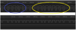
As has been noted by a number of you, the transmission rate is likely to be the most critical requirement. I spent some time aligning the transmission rates and I think I’ve finally got them in good alignment. The transmission of 10 sequences of the 15 bit pattern takes 825.2 mSecs and my program takes 825.6. This difference of only 0.4 mSecs is only about a quarter of the narrow “0” pulse so shouldn’t be a problem. Also I’ve confirmed that the genuine remote only needs to be depressed for 500 msecs for it to be accepted by the controll-a-door so in fact only about 6 sequences are required. I’ve also found that the transmission rate of the genuine remote varies slightly with battery voltage. The battery that was in it when I made my initial measurements was old and I later noted that its voltage dropped to below 8 volts when actually transmitting. When a new battery was installed, the transmission time for 10 sequences actually increased to 827.7 mSecs.
I’ve also thoroughly investigated the pulse width for the “1” and “0” and found that the variation in width of the 08M2 generated pulses is actually less than the genuine remote. Added to this, the width of both lots of pulses (ie from the genuine remote and the 08M2 controlled transmitter) widen significantly when the transmitter is brought closer to the receiver. So again, I’m pretty confident that the width of the generated pulses is not the reason for the controll-a-door not to respond to my simulated signal.
Alan, I do have a genuine Saleae but I don’t think that that will make much difference in this case as I am doing all my timing measurements on a cheap Chinese receiver and not the actual receiver in the Controll-a-door. However, for the reasons given earlier, I don’t think that pulse width is the problem for the old slow signal protocol that is used here.
I feel that there must be something else about this signal that is causing the problem but I can’t imagine what that is, so I’d be grateful for any other suggestions on areas that I can investigate. One thing that I did spend some time on was that I noted that the first sequence after the button was pressed on the genuine remote had a header that was 10.6 mSecs long compared the normal 6.6 mSecs for later sequences and I even altered my code to roughly incorporate that but it made no difference. On later reflection, I expect that the wider header pulse width is probably caused by the very low voltage as the capacitor charges up just after the button is pressed.
Thanks to you too Hippy for providing your programs. I didn’t actually use them as your second one was quite close to mine but I did re-arrange mine so that variable assignment was at the end of the program. Mind you, I still found it very frustrating actually “tuning” the timings and that changes to constants further down in the code often affected other timings whose values were set earlier in the code.
Again, thanks to everyone who offered suggestions and I still welcome more. Also, if someone knows of a commercial product that can be used with this old controll-a-door, please reply with the details.