A couple of weeks ago I asked for help with a circuit using a 14M2 in this thread. Taking the advice offered, I moved my switch inputs, and my servo outputs, so they no longer shared the serial-in and serial-out pins with the programming circuit; and my prototype worked exactly as expected. Attached is the circuit as it stands.
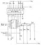
There are four possible position options for the Sw1 and Sw2 (open/open, closed/closed, open/closed, and closed/open) which send the two servos to corresponding positions. Before moving the servos to a new position the program sets B.3, B.4, B.5, C.0, C.1, and C.2 LOW, to extinguish the four LEDs and solid-state relays (installed, but not shown in my diagram). Once the servos have moved to a new position a HIGH is sent to the appropriate 14M2 pin to switch on an LED to indicate which of the four positions the servos are at, and to switch on the appropriate relay.
So far, so good. The prototype is working correctly on my model railway.
So then I built an exact copy, using the same PCB design and the same components (except the solid-state relays are not yet installed), and same program, but it's behaving oddly. The 14M2 programs okay, and the servos move correctly in response to the switch inputs so, presumably, all the resistors are correct value and installed correctly. But the LEDs work in the opposite manner, and more dimly, than they should -- i.e. instead of one being lit at a time, three are lit and one is out. I've visually checked the circuit board under a magnifier and can find no defects. I then measured the voltage at the 14M2 output pins B.3 to B.5 and C.0 to C.2 and found that, for each different switch combo, the pin which should be HIGH measured somewhere between 1.4 and 1.5v, while the other five pins, which should be LOW, measured somewhere between 0.0v and 0.12v. Should a HIGH pin not be at, or around, the supply voltage, which is 5.0v?
What could be causing this behaviour, please? I've already swapped the 14M2, with the same result. Could it be a faulty ULN2803? Or could a solder bridge which I haven't detected yet cause half the 14M2 pins to behave like this -- remember, the inputs on C.3 and C.4 and the servos on B.1 and B.2 seem to be working correctly.