Why are my inputs & outputs high when they should be low?

cianyd

New Member
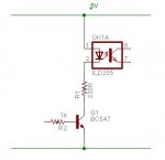
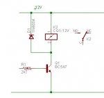
I'm having a problem with my circuit (schematic below). This circuit is an electric match ignition system with continuity check. GPA0 is an input, which reads the continuity circuit. GPA0 is an output, which activates the relay that will allow current to flow into the electric match, igniting it.

For some reason the relays are closed (turned on) when I send a 0/low signal to them, and open (turned off) when I send a 1/high signal to them.

This is problematic because everything pulses whiles the circuit is starting up. As I am running an electric match off this circuit, it would let the firework off everytime I turned the circuit on!

The other problem is that the continuity check circuit is 0/low when there is continuity, and 1/high when there is no continuity (eg when there is not electric match attached).

I must have gone wrong somewhere with my circuit. How do I switch these low/high states around?

Any help appreciated!!

[size=+3]ATTENTION:[/size] This circuit is NOT complete and therfore NOT safe.
 
Last edited:

ylp88

Senior Member
Your inverted relay output operations are probably due to the PNP transistor (BC557) you have in your schematic. With a high output on GPB0, you turn off this PNP transistor which turns off the optocoupler. This also means that the NPN transistor, BC547 is off and the relay is off. The opposite should occur for GPB0 off.

Similarly, for your continuity, when there is no continuity, the optocoupler is off and this means that the input (the logic state at the pointer OUT0) is high due to the 1k pull up. When you have continuity, the optocoupler is on and thus the transistor in it pulls the input pin low (and thus the logic state at OUT0) is low.

The easiest way (and the benefit of using reprogrammable microcontrollers instead of hard-wired systems) is to compensate for these in software.

As for power on fluctuations, perhaps you can tie the reset pin low via a pull down resistor and then connect it to an PICAXE output and the PICAXE can set the state of the IO expander's reset pin and thus hopefully the expander's IO state during the fluctuations.
 

moxhamj

New Member
You could swap the 557 for a 547. Drive the base of the 547 with a 1k resistor. Put the anode of the optocoupler led to 5V. The cathode of the optocoupler goes to the 330R resistor then to the collector of the 547 and the emitter to ground. Similar to the 547 circuit you already have on the other side of the optocoupler but minus the 47k pull down resistor.

You could also temporarily put a led in series with the optocoupler led - then you can see it going on and off.
 

Attachments

Last edited:

hippy

Technical Support
Staff member
This is problematic because everything pulses whiles the circuit is starting up. As I am running an electric match off this circuit, it would let the firework off everytime I turned the circuit on!
[size=+1]Where is the key activated switch between the relay output and the 'match' ?[/size]

[size=+1]Where are the safety critical interlocks ?[/size]

This is why I ( and others ) bang on about the dangers of safety critical systems and are less than encouraging about people without the prerequisite skills getting involved in such things.

At least I suppose you realise it's not safe to a degree and have recognised a level of safety criticalness involved.

I'm not sure why you are using two opto's because they really add nothing towards safety and in fact make the circuit more complex. I am sure you could do any necessary level conversion without such complexity.

Also, I'd make the ignition detect feedback signal to 0V and put a blocking diode near the 'match' to prevent activation current coming from anywhere other than through the relay. In fact, I'd design it entirely differently, the 'match' switched by a remote unit operated by +12V control signals, with hardware, relay-only interlocks and key switches so it can never be armed accidentally or when other than in a safe non-firing condition.

No, I'm afraid I don't have a circuit or design. But the number one question you should be looking at is, how can you ensure that a 'match' is never ignited even if connected when the circuit is convinced it should ignite the 'match'.
 

moxhamj

New Member
Yes, I agree the optocouplers are not really needed - a relay provides isolation of thousands of volts anyway. So instead of the 557/optocoupler/547/relay circuit just replace it with this simple circuit. Picaxes default to low outputs when starting so there should be no chatter on startup.
 

Attachments

Last edited:

cianyd

New Member
[size=+1]Where is the key activated switch between the relay output and the 'match' ?[/size]

[size=+1]Where are the safety critical interlocks ?[/size]
On the circuit I have built there is a toggle switch between the battery and the entire circuit, along with a primary relay which switches the entire +12v rail to the secondary individual output relays (the relay in the above schematic).

On the controller unit a keylock (seperating positive rail battery power) combined with a keypad requires a correct key and pin to activate the panel buttons.

There are many software safety interlocks too taking into account situations such as faulty stuck-on panel buttons amongst others.

I did not include many of the hardware interlocks as the schematic posted above was purely put together in respect to the issues I am experiencing.

This is why I ( and others ) bang on about the dangers of safety critical systems and are less than encouraging about people without the prerequisite skills getting involved in such things.

At least I suppose you realise it's not safe to a degree and have recognised a level of safety criticalness involved.
I am aware of the risk associated with developing such a system. However, this isn't a system that is going to be used commercially and will be extensively tested prior to use in any situation where safety would be of concern. Safety is the number one reason I have sought advice on the best way to both isolate and regulate the relay component.

I'm not sure why you are using two opto's because they really add nothing towards safety and in fact make the circuit more complex. I am sure you could do any necessary level conversion without such complexity.
The optos are there mainly because the Picaxe side of the circuit runs on 3.3v, while the relay side runs on 12v. I didn't think mixing the voltages physically was good idea. Correct me if im wrong though, I was under the impression it was better to be over cautious.

Also, I'd make the ignition detect feedback signal to 0V and put a blocking diode near the 'match' to prevent activation current coming from anywhere other than through the relay. In fact, I'd design it entirely differently, the 'match' switched by a remote unit operated by +12V control signals, with hardware, relay-only interlocks and key switches so it can never be armed accidentally or when other than in a safe non-firing condition.
Cheers for this one, i'm going to add diodes to the circuit. I don't understand how the continuity circuit would work with 0v however, as the connected side of the electric match is connected to 0v also.

No, I'm afraid I don't have a circuit or design. But the number one question you should be looking at is, how can you ensure that a 'match' is never ignited even if connected when the circuit is convinced it should ignite the 'match'.
Maybe I've misunderstood what you're saying here, as this is the whole purpose of the system - to ignite the electric match when instructed to.

I hope the above alleviates some of your concerns over my project. It is purely a hobbyist project and is not intended for use beyond.
 

cianyd

New Member
Your inverted relay output operations are probably due to the PNP transistor (BC557) you have in your schematic. With a high output on GPB0, you turn off this PNP transistor which turns off the optocoupler. This also means that the NPN transistor, BC547 is off and the relay is off. The opposite should occur for GPB0 off.

Similarly, for your continuity, when there is no continuity, the optocoupler is off and this means that the input (the logic state at the pointer OUT0) is high due to the 1k pull up. When you have continuity, the optocoupler is on and thus the transistor in it pulls the input pin low (and thus the logic state at OUT0) is low.

The easiest way (and the benefit of using reprogrammable microcontrollers instead of hard-wired systems) is to compensate for these in software.

As for power on fluctuations, perhaps you can tie the reset pin low via a pull down resistor and then connect it to an PICAXE output and the PICAXE can set the state of the IO expander's reset pin and thus hopefully the expander's IO state during the fluctuations.
Thanks for clearing that up.

Perhaps dealing with these issues in software is the solution, but what I don't understand about the relay module I am using is why it activates the relay on a low signal, and not a high one. It mentions (in the excerpt below) that this is to prevent relay activation during micro-controller resets, however this is seemingly illogical?..

The ET-OPTO RELAY4 board is an OPTO-Isolated 4 channel output board which is used to control the operation of electrical equipment by the use of a TTL +5V control signal. The Relay circuit uses an Opto-Isolated circuit to control the operation and to prevent interference. The optical isolation provides effective isolation by completely isolating the control and load circuits, this is done by using an optical source to close the output contacts of the circuit. The relay closes on logic “0” and opens on a logic “1”, this prevents the relay from switching on during the micro-controller resets or when the board is turned on.
 

hippy

Technical Support
Staff member
On the controller unit a keylock (seperating positive rail battery power) combined with a keypad requires a correct key and pin to activate the panel buttons.

There are many software safety interlocks too taking into account situations such as faulty stuck-on panel buttons amongst others.

I did not include many of the hardware interlocks as the schematic posted above was purely put together in respect to the issues I am experiencing.
That's a fair point but worth mentioning on the circuit itself, because people will grab 'ready made circuits' from the web and not realise they are incomplete or inherently dangerous. And it means I don't have to put my "Danger Will Robinson" hat on :)

I don't understand how the continuity circuit would work with 0v however, as the connected side of the electric match is connected to 0v also.
The existing scheme is effectively a pull-up to +12V to drive the opto, there's current limiting there, but by monitoring the +12V applied to the match with reference to ground, there's even less risk of current coming from any source.

However, you say "continuity circuit", so is it could be to measure that the match is fitted not to monitor ignition power applied as I assumed it was.
 

womai

Senior Member
>I'm not sure why you are using two opto's because they really add nothing
>towards safety and in fact make the circuit more complex. I am sure you
>could do any necessary level conversion without such complexity.

I would feel safer WITH at least one optocoupler in the path. The reason being, the relay is a mechanical piece of hardware, and it has moving parts, i.e. repetitive mechanical stress - what e.g. if some internal piece breaks off and causes a short circuit within the relay? Then the optocoupler acts as a second layer of safety.

Wolfgang
 

BeanieBots

Moderator
A safety critical device will of course be using an appropriately TUV approved safety relay which is designed in such a way that it is impossible for such internal shorts to happen. (that's why they are so damn expensive). So adding an opto-isolator is only adding another layer of potential failure!
Unless, there is a justified reason for extra complexity, it should be avoided.
It is also common practice to active high circuitry. That is because any cable which may become disconnected, is more likely to contact ground (0v) than the required activation line. A circuit that activates at 0v WILL activate if the driver circuit fails, resets or suffers a power failure!
 

BCJKiwi

Senior Member
If I understand you initial query correctly, there are two separate issues;
1. The circuit pulses on startup
2. The circuit, once stabilised behaves opposite to what you expect.

The discussion so far seems to relate to point 2.
Regarding Point1 I would look to the configuration of the MCP23017.
Assuming this behaves similarly to the 23016 which I have used, there are some non-obvious characteristics of these units.
a. the GPIO ports are not on/off. They are always active and the control of the port simply swaps its function between input and output.
b. In the case of the '16 it always starts up one way and does not get to the opposite until you set it. So if you want your default to be the opposite of the chip default, the port function will be opposite to what you what until you initialise the chip.
If this is the cause of the startup pulsing, then changing the 'sense' of the circuit to utilise the default chip port orientation will fix that issue.
 
Last edited:

cianyd

New Member
A safety critical device will of course be using an appropriately TUV approved safety relay which is designed in such a way that it is impossible for such internal shorts to happen. (that's why they are so damn expensive). So adding an opto-isolator is only adding another layer of potential failure!

Unless, there is a justified reason for extra complexity, it should be avoided.
The opto-isolators are purely to seperate the 12v from the 3.3v areas of the circuit.

It is also common practice to active high circuitry. That is because any cable which may become disconnected, is more likely to contact ground (0v) than the required activation line. A circuit that activates at 0v WILL activate if the driver circuit fails, resets or suffers a power failure!
This is what confuses me about the relay circuit - why would a company manufacture a circuit which defies safety and common sense. I purchased the relay circuit ready built from Futurlec (http://futurlec.com/Opto_Relay_4.shtml).

I've uploaded the manual for it; http://www.getbweb.com/stuff/ETOPTORELAY4Manual.pdf.
 

cianyd

New Member
That's a fair point but worth mentioning on the circuit itself, because people will grab 'ready made circuits' from the web and not realise they are incomplete or inherently dangerous. And it means I don't have to put my "Danger Will Robinson" hat on :)
Good point, I will update the schematic with the final design once it's ready. Until then perhaps a warning is in order.

The existing scheme is effectively a pull-up to +12V to drive the opto, there's current limiting there, but by monitoring the +12V applied to the match with reference to ground, there's even less risk of current coming from any source.

However, you say "continuity circuit", so is it could be to measure that the match is fitted not to monitor ignition power applied as I assumed it was.
It is to check that there is an electric match attached to the output. Maybe there is a better way to do this? It was always going to be the trickiest part of the circuit.. I figured that 2 resistors incase of failure would be enough to stop more than 5ma to get through - far less than the amount needed to ignite the match.
 

Mycroft2152

Senior Member
"why would a company manufacture a circuit which defies safety and common sense"

For most logic families it is easier to sink current than to source current. One gate may source 3 milliamps but can sink 30 milliamps. Therefore the rational is manufacturing and fan-out reasons.

What is most important is to have safety interlocks during power up, when the microprocessor outputs are in a "unknown" state.
 

BeanieBots

Moderator
"why would a company manufacture a circuit which defies safety and common sense".

Those are NOT safety relays and it is not described as failsafe.
It does seem to digress from convention but pointing out a minor "design anomoly" as a feature is not unheard of.
 
Top