Viability of Picaxe range finder

jmac5555

New Member
Just wondering if anybody would be able to offer some advice as to whether my proposed (hobby) project is possible.

In essence I am trying to construct a range finder using a 14 pin picaxe chip. Basically I intend to use an infrared emitter to emit a continual beam that will reflect off the object and then be read by an infrared reciever. While this is happening I plan to have a program running within picaxe that starts a counter when the Infrared emitter is acitvated and times how long it takes for the beam to travel to, and reflect of the object ( I do realise that the Picaxe chip will not be able to work at 100% accuracy considering the speeds at which the infrared beam will travel, however i plan to counteract this through manipulation of the final variable). The variable shall be processed through an equation (similar to that used to calculate distance, speed and time), and then the final result shall be displayed on a 4bit LCD module.

Basically, is this project doable.... or has anyone done something similar to this and wishes to offer some advice.

Any help is greatly appreciated =)
 

BeanieBots

Moderator
Welcome to the forum.

In a nutshell, you stand ZERO chance of timing light speed with a PICAXE:eek:

However, the speed of sound is quite possible. Consider ultrasonics.
Modules already exist such as SRF04/SRF08.

You don't specify what range you want to measure.
US can be made to work up to around 10 meters.
 

Tag16c

New Member
If you already have the IR pair you could do a presents / avoidance sensor. This would be the simple application.
To do a distance you will need some kind of trianglization by masking and sweeping your emitter and getting the angle when the beam is seen. (You should look for the center of the angle the beam is received)
This would be much more accurate if the emitter were a laser.
This is not a simple project but doable one
 

hippy

Ex-Staff (retired)
At 299,792,458 metres per second for the speed of light, that's around 300m in 1us, 3ns for 1m, 3ps for 1mm. Way too fast for a PICAXE and any micros I know.

Assuming you could find hardware which will respond quickly enough and afford the high cost of that, one way such short intervals are measured is by charging a capacitor up during that time and then measuring the charge at a more liesurely rate which will be proportionate to time.

This is however almost certainly beyond most hobbyist's skills and budget. Ultra-Sound is much more manageable and pre-build modules take all the hardware complexity out of it - Rev-Ed / Tech-Supplies sell the SRF005 which would make the task easy.
 

bgrabowski

Senior Member
The way to use IR to measure distance is by use of the analogue-to-digital converter. The best explanation I have seen as to how to do this comes from the www.micromouseonline.com website.

Have a look at Martin Barratt's brilliant treatment of this complex subject at:
http://www.micromouseonline.com/files/minos09/minos09-martin-barratt.pdf

The UK micromouse community have excellent documentation dealing with d.c. motor control, stepper control, odometry, rangefinding and maze solving.
 

hippy

Ex-Staff (retired)
The intensity of relected light can be used to determine range as suggested by bgrabowski, but this will depend upon what the surface doing the reflecting is; different surfaces have different absorptions and a darker surface will reduce the reflected light making it appear further away than a whiter surface. Okay for micromouse or other situation where the reflecting surfaces are generally known and uniform, but not for a general case.

Is this for a micromouse ? What sort of ranges ( minimum and maximum ) are you looking at measuring ?
 

slurp

Senior Member
While knocking a short video together at the weekend, I demonstrated Hippy's comments on dark surfaces. The black surface was undetected with Sharp's IS471F sensor, normally this would give detection at 50-70mm.

http://www.youtube.com/watch?v=dSs1VGr_UbI

I've seen other instances where angled reflective surfaces cease to detect. Thing about angled mirrors bouncing light away from the light source.

regards,
Colin
 

jmac5555

New Member
Thanks for all the words of advice and help. Upon reflection the SRF005 looks perfect to suit my needs (EG reasonably low cost range finder to ~10m). Can anyone provide a link to a site that sells them?

Thanks in advance
 

BeanieBots

Moderator
10m is "pushing the boundaries" for US range finding with an SRF05.
It IS capable of it but only under favourable conditions.
(from memory, the spec is 6m)

Devantech do a full range of units, might be worth a browse.
 

testerrrs

New Member
I built a similar thing, see project log and writeup here:

http://www.hexoc.com/wb/pages/ultrasound-ranger.php

Didn't want to pay for the SRF005, so did it all myself.

I now have a neater and more elegant circuit for distance finding if you decide to do it this way. Post back if you want more info.

The one in the link works extraordinarily well, however. Accurate to 1cm under 1m and accurate to 2-3cm up to 5m. Doesn't work at >5m range, but could be easily modified to do so.
 

slurp

Senior Member
I now have a neater and more elegant circuit for distance finding if you decide to do it this way. Post back if you want more info.
I'm certainly interested to know more.... mind you I'm only working to about 6-700mm and don't need the accuracy.

Best regards,
Colin
 

testerrrs

New Member
I found this design somewhere on the internet so I take no credit for it.

In my testing I made several modifications to increase accuracy etc, but it was a few years ago so I can't remember exactly what.

I remember it worked very well and had better accuracy at short range than the one in my above post, although it had a max range of about 1.5m.

See attachments for code and schematic.

----------------

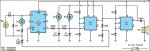
Ultrasonic Rangefinder


This circuit uses a PICAXE-08 as the basis of a simple ultrasonic rangefinder which has a resolution of 1.7mm and a maximum practical range of about 120mm.

A novel approach is used to interface the ultrasonic receiver to the PICAXE, in theory eliminating the need for any amplification, rectification, filtering or threshold detection that would typically be employed.

The PICAXE detects a signal from the ultrasonic receiver (RX1) on input 1 (pin 6). Being a digital input, at least 2V (nominal) must be applied to this pin before it will be read as a logic "high".

Pedestal voltage

In order to detect a much smaller signal level than this from the receiver, a DC "pedestal" voltage is applied to the pin, lifting it up to a value just below the logic high threshold. In this condition, even a small signal from the receiver is sufficient to exceed the threshold voltage and thus be detected by the PICAXE.

The pedestal voltage is provided by capacitor C1, which is connected in series with the receiver. The voltage on C1 is initialised at the start of every measurement cycle using the aforementioned port pin and a simple software sequence.

First, the capacitor is charged until the voltage applied to pin 6 reads "high". This is achieved by alternately making pin 6 a high output, which charges C1 via D1 and the 100kO and 1MO resistors, and making it an input to read its logic state.

Next, the capacitor is discharged to the point where the input samples "low" 30 consecutive times, thereby minimising the chance that noise (either electrical or acoustic) will cause false triggering. This is achieved by alternately making pin 6 a low output, which discharges C1 via the 1MO resistor, and making it an input to read its logic state.

Once initialisation is complete, pin 6 is set as an input, ready to receive a signal from RX1. Loading of the receiver signal is kept to a minimum by the very high impedance of the digital input. In addition, any voltage produced across its terminals is too small to forward-bias D1, so the 100kO resistor is effectively out of circuit.

Amplification

Whilst in theory not required for this circuit, I have included an LM741 Operational Amplifier. The receiver is connected between the two input pins. The receiver is quite selective, so when a 40kHz signal is picked up, the small voltage generated by the receiver is amplified around 1000 times by this system. The output is then fed into the pedestal capacitor (C1) via a 0.02μF coupling capacitor.

By doing this, the range of the system is increased considerably to around 300mm. In addition, it gives more reliable operation in that a flat surface is not required for a signal to be received on its return.


Transmitter

The ultrasonic frequency required for the transmit signal is generated by a 555 timer configured as a 40kHz free-running oscillator. The frequency of oscillation is set by the 10kO resistors and 1nF capacitor connected to pins 2 & 6. It drives the ultrasonic transmitter via a 100nF coupling capacitor.

The reset input (pin 4) of IC3 is controlled by a second 555 timer. This timer is configured as a monostable, producing a 300µs wide "transmit enable" pulse as determined by the 1nF capacitor and 270kO resistor.

A low-going pulse on pin 3 of the PICAXE triggers the monostable, generating a 300µs transmit burst. The trigger pulse is delayed by about 5ms by an RC network. This is required because the PICAXE takes a small amount of time from the finishing of running one command to the beginning of running another. The delay makes sure that the PICAXE has run the ‘pulsin’ command before the burst of ultrasound is fired.

The 5ms delay works as follows: The PICAXE output on pin 3 is normally high, holding the 47nF capacitor (C2) charged via the 270O resistor. In turn, the 4.7nF capacitor (C3) is charged via the 2.7MO resistor. This holds the trigger input of IC2 high.

The PICAXE sends a transmit burst by briefly taking pin 3 low, then setting it as an input. This discharges capacitor C2 but does not hold it discharged. C3 then slowly discharges into C2 via the 2.7MO resistor.

After about 5ms, the voltage on C3 falls below the 1/3 Vcc threshold of IC2’s input (pin 2) and triggers it, generating a high output on pin 3 for about 300µs. Diodes D2 and D3 are included to ensure that IC2 is not retriggered. They charge C2 and C3 while the output of IC2 is high, taking the trigger input of IC2 high.

The transmit enable signal at pin 3 of IC2 is fed back to the PICAXE receiver input on pin 6 via the negative end of C1. The voltage divider formed by the 10kO and 100kO resistors raise the negative end of C1 to about 0.5V during the transmit burst. This is sufficient to raise pin 6 above the logic high threshold voltage.

After the PICAXE initiates the transmit burst, it uses the pulsin command to measure the length of the negative-going pulse at pin 6, with a resolution of 10µs. This pulse is formed from the trailing edge of the transmit enable pulse and the rising edge which shows reception of the first echo. There is no attempt to check that the receiver is receiving a 40kHz signal but as the transducer is highly selective, this method is quite reliable.

When the pulsin command completes, the PICAXE again makes pin 3 a high output to charge the two capacitors, ready for the next transmit burst.

Second burst

The PICAXE now sends a second transmit burst for the sole purpose of measuring its length. The time from the pulsin command is then added to the first measurement to correct for the length of the transmit burst. The result is then multiplied by a constant to convert it into millimetres and saved in the distance variable.
 

Attachments

inglewoodpete

Senior Member
From my experiments with ultrasound about 25 years ago, the sensitivity of the receiver could be enhanced by inserting a narrow-bandpass amplifier immediately after the US receive transducer module. I presume that the transducers haven't changed much since then.

The amplifer was an operational amplifier with an LC filter inserted in the feedback path. The capacitor in the filter had to be tweaked (with a smaller capacitor in parallel) to get the amplifier closely tuned to 40kHz (or the required US frequency).
 
Top