Hi,
No, it generally MUST be done with some form of external hardware. The
first thing that a PICaxe does
before it executes
any program code is to check the level on the serial input pin. If the level is High (logic 1) then it enters the program/download mode, which it confirms by raising the Serial Output pin High.
If the "Auxiliary" input might be High during the first few hundred ms after power is applied (or if the PICaxe resets for any other reason), then basically it's necessary to put a logic "gate" (of some form) in series with the "auxiliary digital input" on the Programming Input. Generally one would fit a hardware switch of some type, but it may be possible to use just a diode or a careful choice of resistor values to act as the gate. Of course nearly all the pins of an M2 or X2 are "floating" (configured as inputs) during the starting sequence, so the controlling input of the "gate" would need to be biassed to the "gate closed" mode by a resistor. Then when the DISCONNECT has been executed the controlling pin can open the gate. But that might require an additional pin, which largely defeats the whole object of trying to use the serial input as an additional pin !
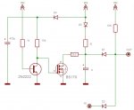
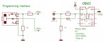
I do have a method to allow the PICaxe to gate a logic signal onto the serial input pin, without the need for another pin, but it's quite an "advanced" method: Firstly, the programming signal (which must remain low at all times except when actually programming) needs to be connected to the programming input by a much higher resistance than the usual 22k (say 100k or more). Then the auxiliary digital signal is connected to the programming input via a diode, so that it can only pull the input Low (i.e. anode to the pin).
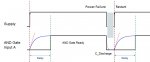
The "trick" then is for the program to execute a DISCONNECT and then enable the "Weak Pullup Resistor" on the programming input pin. That value is quite high (about 30 k) which is why it was necessary to increase the input pull-down resistance. Now, the pin can rise to a High level, unless the auxiliary input pulls it Low (via the diode).
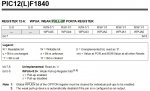
Unfortunately there's one more twist: the PE won't accept a PULLUP command for the programming input pin

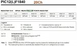
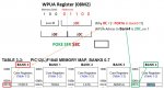
So it's necessary to use a POKESFR command, which for 08, 14 and 20 pin M2s is:
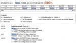
POKESFR WPUA,%00100000 or simply
POKESFR $8C,32.
Cheers, Alan.