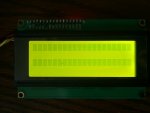
Using Arduino IIC / I2C Serial 3.2" LCD 2004 Module Display
- Thread starter Pekari
- Start date
First thing I would do is try sending it 0 - 255 in order and see if it does anything.
Use a for loop, with a pause and some serout commands (to debug from the computer), then you can see which commands affect the LCD.")
Note: This is probably not the way most would do it...
Jamster
Use a for loop, with a pause and some serout commands (to debug from the computer), then you can see which commands affect the LCD.
Note: This is probably not the way most would do it...
Jamster
The board has a PCF8574 i2c i/o expander on it.
This is a 'dumb' i2c-parallel chip with none of the intelligence of other more common serial LCD modules.
So basically you have to work out which on the 8 i/o pins are connected to which LCD pin and then completely hard code all the LCD control codes / initialisation routines.
That can be done, but all in all it would probably be much simpler to buy an 'intelligent' i2c or serial module like the AXE033 or AXE133.
I don't see any difficuly in using this with a PICAXE as it's a I2C bus. Reference to the manual will give you the basic outline of how to communciation with it at address 27.
hi2cout 27,(254,1) ; clear screeen
hi2cout 27,("Hello World");
Use the same commands for the standard LED display driver chip such as HD44780, etc
hi2cout 27,(254,1) ; clear screeen
hi2cout 27,("Hello World");
Use the same commands for the standard LED display driver chip such as HD44780, etc
I have used this code:
I also have try address $27 and i2cbyte.
Nothing happens...
Code:
#picaxe 18m2
init:
	i2cslave 27,i2cslow,i2cword ' set up i2cslave for LCD
	pause 500 ' wait for display to initialise
	writei2c 0,(254,1) ; clear screen
	pause 200
	writei2c 0,("Hello World",255);
pause 200Nothing happens...
See technical's post:I have used this code:
Nothing happens...Code:#picaxe 18m2 init: i2cslave 27,i2cslow,i2cword ' set up i2cslave for LCD pause 500 ' wait for display to initialise writei2c 0,(254,1) ; clear screen pause 200 writei2c 0,("Hello World",255); pause 200
As the i2c I/O expander only has eight I/O pins, the LCD will be controlled using the 4-bit interface and you have to send two bytes to pulse the Enable pin. This would be quite slow, very difficult to use, program memory hogging and generally not very good.The board has a PCF8574 i2c i/o expander on it.
This is a 'dumb' i2c-parallel chip with none of the intelligence of other more common serial LCD modules.
So basically you have to work out which on the 8 i/o pins are connected to which LCD pin and then completely hard code all the LCD control codes / initialisation routines.
That can be done, but all in all it would probably be much simpler to buy an 'intelligent' i2c or serial module like the AXE033 or AXE133.
My view on this: This LCD combines the disadvantages of both intelligent serial (expensive) and 4-bit shift register serial (complicated) and with none of the advantages. It would be easier to do 8-bit shift register control with separate enable and register select lines.
No. Only communications to the i2c port expander to control the LCD are. However you must first find out which pins on the port expander's port connect where on the LCD.Do I have to split address 27 to two part too?
I can't believe it's that complicated...
I've got to ask:
1. Have you connected the SDA (Data) line to the correct pin on the PICAXE? - - which pin on which device.
2. Have you connected the SCL (Clock) line to the correct pin on the PICAXE? - - which pin on which device.
Is there a link on the daughter board that might switch it between serial and I2C mode?
Do you have a data sheet for the screen controller?
g6ejd: I don't think you understand... The chip in place is an IO expander, not an LCD driver... That means he has to use the 4bit interface through the I2c chip - not easy.
I think the easiest method would be to unsolder the chip add-on board from the LCD board then use the two seperately, the LCD with the normal 4bit interface and the I2c expander for something completely different.
Jamster
I think the easiest method would be to unsolder the chip add-on board from the LCD board then use the two seperately, the LCD with the normal 4bit interface and the I2c expander for something completely different.
Jamster
@g6ejd:
I use PICAXE 18M2.
Pins are: SDA = pin 7 and SCL = pin 10.
Both pins have 5.1 k pull up-resistors to +Vcc.
You can see board in my post #1 and datasheets from my post #6.
@Jamster:
Ok, thanks. I think I'm maybe masochist when I buy this... I'm clad I didn't buy 3 pcs this display!!!
Still I try to found some use to this.
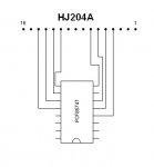
And I'm not sure if that LCD datasheet is exact, because there also exist 8-bit 20x4 LCD:s and I'm not sure if this is one of them.
This LCD is HJ204A. I did'n found exact datasheet.
I use PICAXE 18M2.
Pins are: SDA = pin 7 and SCL = pin 10.
Both pins have 5.1 k pull up-resistors to +Vcc.
You can see board in my post #1 and datasheets from my post #6.
@Jamster:
Ok, thanks. I think I'm maybe masochist when I buy this... I'm clad I didn't buy 3 pcs this display!!!
Still I try to found some use to this.
And I'm not sure if that LCD datasheet is exact, because there also exist 8-bit 20x4 LCD:s and I'm not sure if this is one of them.
This LCD is HJ204A. I did'n found exact datasheet.
Last edited:
You need the LCD117 chip from Peter Anderson:
http://www.phanderson.com/lcd106/lcd107.html
MUCH MUCH MUCH easier then trying to do it with an I2C interface chip and working out all the codes to get anything to come up on the screen...
204 series is 20 character and 4 rows.
http://www.phanderson.com/lcd106/lcd107.html
MUCH MUCH MUCH easier then trying to do it with an I2C interface chip and working out all the codes to get anything to come up on the screen...
204 series is 20 character and 4 rows.
Now I'm trying with this code:
Is this the right direction?
Code:
#picaxe 18m2
init:
	i2cslave 27,i2cslow,i2cbyte ' set up i2cslave for LCD
	pause 500 ' wait for display to initialise
	hi2cout 0,(0,3)
	pause 10
	hi2cout 0,(0,3)
	pause 10
	hi2cout 0,(0,3)
	pause 200
	hi2cout 0,(0,3)
	pause 20
	hi2cout 0,(8,0)
	pause 20
	hi2cout 0,(1,0)
	pause 20
hi2cout 0,(6,0)Yes.
The data sheet suggest the display starts in 8-bit mode. So you need to reverse your data as it's DB5 and DB4 that are the control bits, so: 0 0 1 1 x x x x is Hex 30 or &30
hi2out 0,(&30) ; & toi denote hex format
pause 10
hi2out 0,(&30)
pause 10
hi2out 0,(&30)
; no other initialisation required other than a clear screen maybe
pause 10
hi2out 0,("hello")
The data bits to use and send out will depend on how the PCF8574 to LCD interface is wired on the module.
It will also be necessary to control all of the LCD control lines and in the correct sequence; for example, send Data and RS with E low, then the same with E high, and finally the same with E low again. So to 'send one byte to the LCD' will likely require four bytes to be sent over I2C because it is in 4-bit mode.
Note that the PCF8574 doesn't use an 'address' in the data sent to write to the display, but using 0 should not cause problems as that simply sets all outputs low. Alternatively the first byte of I2C data could be sent as the address.
The most sensible way to do this is to use standard PICAXE to parallel interfacing code, alter the 'init', 'wrdat' and 'wrcmd' parts to send via I2C rather than output directly to the port. This is the classic 'hardware abstraction' approach and will be far easier than changing all the code throughout a program. That can be done when it's all working if it's felt necessary to do so.
Added: The first step is to determine the PCF8574 to LCD signal wiring. Without that you cannot write the PICAXE I2C code.
Last edited:
Now I try with this code:
Nothing...
Circuit:
Code:
#picaxe 18m2
init:
	i2cslave 27,i2cslow,i2cbyte ' set up i2cslave for LCD
	pause 500 ' wait for display to initialise
	hi2cout 27,($30)
	pause 10
	hi2cout 27,($30)
	pause 10
	hi2cout 27,($30)
	pause 200
	hi2cout 27,($30)
	pause 20
	hi2cout 27,($8)
	pause 20
	hi2cout 27,($1)
	pause 200
	hi2cout 27,($4)
	pause 200
	hi2cout 27,("Hello World");
pause 200Circuit:
You still havent grasped that this is not an intelligent driver, and so you will *never* be able to do something like:
hi2cout 27,("Hello World");
To use this unit you will have to write complex unique subroutines to initialise the screen in 4 bit mode, and then to send each character or each control code one by one (ie a i2c command for each of the two 4 bit nibbles, and another i2c command to pulse E in between each nibble).
Once again, it will be much, much easier to ditch this unit completely and buy a serial controller instead if you want to use the type of command structure you are currently attempting to use.
Very probably, but it's worth looking at the AXE134Y 20x4 OLED which seems comparably priced to what you have. It will be very much easier to interface to using serial.Could AXE132 drive this LCD?
Just for amusement; to send "Hello World" to this I2C display would require something like -
HI2cOut $14, ( $34, $14, $18, $38, $18, $16, $36, $16, $15, $35, $15, $16, $36, $16, $1C, $3C, $1C, $16, $36, $16, $1C, $3C, $1C, $16, $36, $16, $1F, $3F, $1F, $17, $37, $17, $17, $37, $17, $12, $32, $12, $10, $30, $10, $15, $35, $15, $17, $37, $17, $16, $36, $16, $1F, $3F, $1F, $17, $37, $17, $12, $32, $12, $16, $36, $16, $1C, $3C, $1C, $16, $36, $16, $14, $34, $14 )
That's a full 113 bytes or so compared to the 24 used for serial output, and you have to work out what each byte to send is.
That's obviously not the way to have to do it. Applying hardware abstraction would allow just the output routines to be written similar to below. The SYMBOL commands have to be set right and you mustn't use 'b1' elsewhere in the code. Every byte sent to the display has to be via a call to one of the two routines. That's far less efficient or as easy to use as serial.
Code:
Symbol bitD0 = bit8
Symbol bitD1 = bit9
Symbol bitD2 = bit10
Symbol bitD3 = bit11
Symbol bitRS = bit12
Symbol bitE  = bit13

SendB0AsCommandByte:

  bitRS = 0

SendB0AsDataByte:

  bitD0 = bit4      ; Send msb first
  bitD1 = bit5
  bitD2 = bit6
  bitD3 = bit7

  bitE  = 1
  b2    = b1        ; b2 holds msb with E set
  bitE  = 0         ; b1 holds msb with E clear

  HI2cOut b1, ( b2, b1 )

  bitD0 = bit0      ; Send lsb second
  bitD1 = bit1
  bitD2 = bit2
  bitD3 = bit3

  bitE  = 1
  b2    = b1        ; b2 holds lsb with E set
  bitE  = 0         ; b1 holds lsb with E clear

  HI2cOut b1, ( b2, b1 )

  bitRS = 1         ; Send data byte next time

ReturnNo, you need to determine what the PCF8574 signal connections are to the LCD, need to work out which bits control which LCD signal. Without that you won't likely be going anywhere.Maybe next I need to learn how to clear display.
Input bits to output are here, PCF8574T datasheet in the page 11.
And this is repaired circuit:
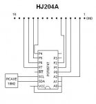
Like you can see, INT and P3 isn't connected to anywhere.
And this is repaired circuit:
Like you can see, INT and P3 isn't connected to anywhere.
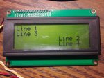
That attached may hopefully put something up on the display ...
Attachments
-
2.2 KB Views: 459
Yes, but still it doesnt light when that code is working. In start it will flash but go off when program starts.Isn't the LED controlled manually by the jumper link on the back?
Code:
 HI2cSetup I2CMASTER, $4E, I2CSLOW, I2CBYTE

  b0 = $33 : Gosub SendB0AsInitByte 'LED will go off in this line of code.
Last edited:
Does the backlight come on if you use b0 = $3B ? If yes, then that means that P3 is actually connected to a transistor that controls the backlight.Yes, but still it doesnt light when that code is working. In start it will flash but go off when program starts.
Code:HI2cSetup I2CMASTER, $4E, I2CSLOW, I2CBYTE b0 = $33 : Gosub SendB0AsInitByte 'LED will go off in this line of code.
"It will not light with that" sounds like an assumption rather than fact. Did you actually try it?No, it will not light with that.
Is there a transistor controlling the backlight? Where does it connect to? Remember that if it's bipolar then there will be a base resistor which will make the continuity checker report no continuity.
Of course I have try it! How else I could say that?
I also try put it to next line too. I have put command "end" to next of that line to see if LED will stay light.
There may be transistor on the other side of board, but I can't measure it because there isn't space so much.
Jumper link is connected to Vcc and controlling is in kathode side.
I also try put it to next line too. I have put command "end" to next of that line to see if LED will stay light.
There may be transistor on the other side of board, but I can't measure it because there isn't space so much.
Jumper link is connected to Vcc and controlling is in kathode side.
Ok. Is there a transistor controlling the backlight?Of course I have try it! How else I could say that?
There IS some transistor in the other side of LCM1602 IIC V1 -board but I don't know if it is controlling it and I can't measure it like I wrote.
I check the circuit:
LED controller is in the green board, not this little black board where that transistor is.
In green board aren't any transistor. There is these 5 IC and 8 resistors which must control backlight LEDs.
I check the circuit:
LED controller is in the green board, not this little black board where that transistor is.
In green board aren't any transistor. There is these 5 IC and 8 resistors which must control backlight LEDs.
Can you desolder the black board from the connector?There IS some transistor in the other side of LCM1602 IIC V1 -board but I don't know if it is controlling it and I can't measure it like I wrote.
I check the circuit:
LED controller is in the green board, not this little black board where that transistor is.
In green board aren't any transistor. There is these 5 IC and 8 resistors which must control backlight LEDs.