Using a transistor input

tegwin

New Member
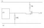
I need to input 1.5V logic into the PIC, so have decided to use a BC184L NPN transistor.

Would this be the correct layout to do the job?


I can get the transistor to switch an LED when a 1.5V HIGH is supplied to the base...
 

Attachments

Michael 2727

Senior Member
Where did you get the 1.5V Logic figure from ?
Normally -
Logic High is 2/3 supply and above.
Logic Low is 1/3 supply and below.

What voltage will the idle state be at the start ?
A Red LED has a 1.5V Forward Drop you may be
able to incorporate this feature.

A little more info will get you a lot better answer.
 

tegwin

New Member
Im using a temperature display unit that gives a 1.5V output when a predefined temperature is reached.

The output sits at 0V until the "temperature alarm" is triggered, this causes the output pin to go to 1.5V (supply voltage for the temp unit)

I need to feed this 1.5V signal into a digital input on the PIC, hence the need for a transistor to step this signal up to 5V.

Hope that clarifies things
 

BeanieBots

Moderator
That circuit won't do what you want.
The simplest would be to use a NPN transistor in inverting mode.
Connect emitter to 0v and pull the collector up to 5v with 10k
Fit a 1k between your temperature device and the base.
The bottom end of the 10k goes to the PICAXE.
The signal will be inverted, ie when the probe is high, the PICAXE will see low.

And please, could people pretty prease, stick to the convention of inputs to the left flowing to the right when drawing diagrams.
 

gengis

New Member
That wouldn't be the way to do it.

Always good practice to add some current limiting to the base of the transistor. Add a resistor in series with the base. 4.7 K should be good. Your thermostat may already limit current - but you have to know that in advance, so be safe and use a resistor.

Your circuit should be Emitter to ground - then take the output to the picaxe from the 5K resistor that goes to +5. When you apply 1.5 V to your base via the current limiting resistor, the base/emitter junction should measure .6 volts or so to ground and the collector should be very low with respect to ground also .3-.7 volts. With an input of less than .5 volts or less to the base your collector should read 5V (logic high for the picaxe).

The 10K is unnecesary unless that's all you have - then use it as a base current limiting resistor instead of the 4.7K I suggested. Transistor you are using has a gain of 100 - that means you only need microamps to turn it on with a 1 ma (5V/5,000) collector load.

Can't supply a schematic - I'm away from my computer

That's all there is to it except your logic is reversed now and your program has to reflect that change. Input pin of the 'axe will have a logic low (~0-.6 Volts) when the 1.5 is present and a logic high (5V) when the 1.5 is input signal is below ~.5 volts.

Check it out on the breadboard to make sure it works as expected then connect to the picaxe input.

If the logic reversal is intollerable to you - use two transistors for an input - one to reverse the signal again. One NPN driving another NPN - both emitters grounded.

You can't use a PNP transistor your input (high or low) will turn it on, it won't turn off without using one more transistor - an NPN to ground so it switches from 0 to 5 volts.
 

hippy

Technical Support
Staff member
The easiest solution would be to take the signal to an analogue input and use READADC, then you wouldn't need any interfacing components.
 

tegwin

New Member
Chears guys...

Transistor has gone in the bin and im now using analogue inputs with great success....

Such a simple solution :-D
 

Michael 2727

Senior Member
I'd use the ADC and Readadc also.
With a 5V supply 1.5V should give you
an ADC of 179 or so, or is that 76, I can
never remember, getting old.

PS: For reliable operation, in case you are
using one of those 3 Button Cell, LCD type
thermostats, you need to join the 0V or
Earth together on both devices.

Or better still use the same supply for both units.
 
Last edited:

BeanieBots

Moderator
1.5v into ADC on a PICAXE @ 5v supply will give:-
76 for ReadADC and
306 for ReadADC10,
Hence, to use ReadADC for detecting a mid point threshold, you should be testing against either 38 or 153 depending on which command is used.
Using 10-bit seems a bit pointless so ReadADC and test for above or below 38 seems the most obvious noise immune way to go.
 
Top