Use of touch pins

The following is from manual 2 (7.9.1 10/2013) p. 248 about the touch16 command:

IMPORTANT - Never ‘directly touch’ a touch sensor (e.g. a piece of bare wire)!
A touch sensor must be electrically isolated from the end user.

I guess that is to prevent damage by electrostatic discharge. However, a series resistor for electrostatic protection between finger and c.4 on a 8M2 works quite well up to several megaohms.
I find this method very tempting, and would appreciate opinions from the forum on possible chip damage.

Thanks!
 

Technical

Technical Support
Staff member
Touch sensing is design based upon a capacitance system, hence you shouldn't use direct touch or resistance.

So touching won't generally damage your chip (or you) but won't work as intended.
 

AllyCat

Senior Member
Hi,

Yes, a resistive connection might actually "stop" the touch oscillator, rather than just "pulling" its frequency (which the touch detector measures).

Also, the "equivalent capacitance" of a human body is about 1 nF and can become charged to tens of kilovolts ("static elecricity"). That could be enough energy to damage the PICaxe, but not if coupled only through the few pF of a typical "touch" plate

Cheers, Alan.
 

inglewoodpete

Senior Member
I have used the touch inputs on a 28X2 in a 3x3 pattern of 9 pads, with PICAXE also driving 9 LEDs.

My experience:
  • The touch sensitivity and background readings vary pin-to-pin.
  • The readings and background reading will change depending on the current flowing through other pins in the same port (Eg Port A, B or C)
  • The thinner the dielectric the better.
I ended up reading each pad 10 times a second using a timer interrupt. A running average was held for each pin so that a comparison could be made to determine if a touch had occurred. The set up eventually proved to be reliable but required a lot of development and testing.

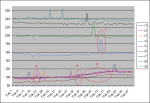
The attached image shows the 9 channels' data logged over a period to show how different touch-pads behaved. Area (D) shows how the average readings rose as more LEDs were turned on in the same port. Note that the uppermost trace shows the average reading actually fell slightly as more outputs were turned on. Touching some pins also produced a level change on other pins (A, B and C). If you are using less pins, you could experiment to find the most sensitive ones.
TouchOutput 20.png
 
Very interesting , thank you for sharing! The encircled little peaks is precisely what I observed, except from a baseline of zero. That the readings depended on other pins is new to me, I have to look into that.

My experience is solely with C.4 of an old 08M2+ on an AXE092 board. It worked well, with a barely noticeable delay, depending on resistor value (series res.).

Readings: 0 - 15 with no touch, climbing to 255 in 2 steps with touch. Seemingly very easy to use.. but now I understand it might not be that simple.

Also, using a 1 m "antenna" instead of a finger, produced same results. So may be voltage noise is being measured by the chip? It would be interesting to know more about how this works, but any attempt to check this with a 10Mohm osciloscope probe failed, probably because the impedance into C.4 is very high.


Anyway, - this works so well, that I will use the method in a current project, using say 100kohm to protect the chip. The small delay mentioned, is just a bonus, as this reduces sensivity and possible false triggering
 

Circuit

Senior Member
Touch sensing technology is far more involved than the simple capacitative touch switching that is accomplishable with a PICAXE chip. I was drawn into this by the very substantial difference in operational stability between what I could achieve with PICAXE chips and the astonishing stability and reliability of the touch switches on the outside of my car. My car locks by touching the front of the door handle; it unlocks when it detects my hand on the inside of the handle, ready to pull open. It works whether I have my gloves on or not; when the handle is wet or dry or even frost-covered. In the heat of summer or the freezing depths of winter, the touch control remains always reliable. Looking into the technology reveals a number of very sophisticated dedicated capacitative touch switch integrated circuits - quite an array of them made by MicroChip. One has to recognise that the PICAXE chip is primarily a tool for education and the incorporation of the touch feature in the latest chips is fascinating and useful but can never be a match for the complex algorithms built into the dedicated touch controllers. Issues with noise immunity, cross-talk and so forth remain. Nevertheless, a useful document entitled "Techniques for Robust Touch Sensing Design" is published by Microchip and gives some useful guidelines on the actual sensor plate design. http://ww1.microchip.com/downloads/en/AppNotes/00001334B.pdf
 

AllyCat

Senior Member
Hi,

using say 100kohm to protect the chip.
Well, Ohms Law says 10 kV and 100 kohms gives 100 mA, with a time constant of 100 ms (with 1 nF); I don't know if a PICaxe will always stand that. Maybe rubber soles and nylon carpets are less common than they used to be, but most chips are still supplied in Electrostatic protection packaging. ;)

Yes, it's interesting that Microchip make some excellent "dedicated" chips ("linear" thermistors are another example), yet IMHO the PIC{axe} implementations are sometimes rather "horrid" (particularly readinternaltemp). Perhaps it's to try to sell their dedicated chips?

Personally, I'd only ever use touch16 not touch. But there are plenty of Microchip Application Notes on touch sensing (and more information in the relevant "base" PIC Data Sheets), which makes one wonder: Why so many? ;)

Cheers, Alan.
 
Yes, Why so many application notes? May be because it is obviously A LOT more complicated than using a mech switch.

Regarding chip protection, the PIC12F683 (08M) datasheet specifies max 20mA continous input clamp current. May be the series resistor should be increased to 1Mohm.

To conclude so far: If I were to make a professional product, I would certainly go with you, Alan, but doing a hobby project, - if the chip is safe, it works well and is the simplest solution in my project ... I just can't resist this experiment!
 

erco

Senior Member
@inglewoodpete: Thanks for that VERY interesting and useful chart. I've played with the touch sensor a bit and the calibration definitely changes day to day. Factors seem to include humidity, moon phase, biorhythm, and sun spot activity. Nonetheless they are magical and fun to play with. Dedicated touch sensor modules are also rife on Ebay. They are cheap and work great, but the touch pads are too close for my big fingers.

Below is a fun application I came up with using three penny touch sensors on a 20M2.

 
Top