Use interrupts with VSM?
- Thread starter jims
- Start date
Talking to myself
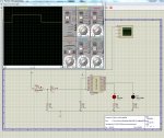
I believe that I need to explain why I asked about "interrupts in VSM". Have been trying (unsuccessfully) to make this code work with the attached VSM schematic. Probably overlooking something obvious. Really do need some help.
.
Thanks in advance...Jims
I believe that I need to explain why I asked about "interrupts in VSM". Have been trying (unsuccessfully) to make this code work with the attached VSM schematic. Probably overlooking something obvious. Really do need some help.
Code:
	'############################
	'#PICAXE 20M2 controller.U2,
	'############################


symbol int_req=pinC.1	'C.1 (pin 9).
symbol RLED=B.3		'B.3 (pin 15).
symbol GLED=B.2		'B.2 (pin 16).


#picaxe 20m2
setfreq m4
pause 1000		'Pause to initialize system
pause 30
setint %00000010,%00000010	'Enable interrupt ON; C.1 (pin 9).


idle:			'######################################
			'#Routine waits for interrupt request
			'#from U1 on C.1 (pin 9).
			'######################################

  	do

 	 high RLED		'Turn RLED ON.

 	 pause 100

 	loop


interrupt:		'##Interrupt detected.


  	low RLED		'Turn RLED OFF if get interrupt.

  	 pause 500

	high GLED		'Turn GLED ON if rcv serial data.

   	 pause 1000

  	low GLED		'Turn GLED OFF if get this far.

 	 pause 500

 	setint %00000010,%00000010	'Enable interrupt ON; C.1 (pin 9).

returnThanks in advance...Jims
Attachments
-
 247.3 KB Views: 14
Thank you hippy. I have attached the 2 files as you requested. Also, want to let you know that the .BAS files runs a expected in the PICAXE PE.The SETINT demo provided with VSM seems to work.
Please post your .DSN and .BAS files and we can see what happens when we run those.
Jims
Attachments
-
977 bytes Views: 12
-
118.6 KB Views: 6
Thank you. Tried C.3 & it now works "like a charm". Figured there must be a VSM problem since C.1 worked on a real-life bread board circuit & on the PE simulator. Jims
There does seem to be a 20M2 interrupt issue on C.1 or C.2 in VSM, the other pins (C.3-C.5) work as expected.
Sorry about that, we'll have to look into it. The real chip will be fine.
If possible try VSM simulating on C.3, C.4 or C.5 instead for now.
A small patch download (4.0.5) to fix this issue is now online at www.picaxe.com/vsm
Thank you "technical". I've downloaded the patch but haven't had time to check it yet. Jims
A small patch download (4.0.5) to fix this issue is now online at www.picaxe.com/vsm
Tried it & the patch works "as advertised". You folks sure give great customer service. Our decision to use PICAXE was the right one!!!
Jims
Jims
Thank you "technical". I've downloaded the patch but haven't had time to check it yet. Jims