USB host

DrWho

New Member
Maxim_IC offers EVKit based on the MAX3421 - USB host IC, that can be directly connected to Arduino.
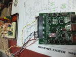
If AXE401 development board is compatible with Arduino (I/Os), is it possible to program PICAXE 28X2 on the AXE401 board so when connected with MAX3421-EVkit would work as an USB host?
 
Last edited:

Dippy

Moderator
Please provide us with links ... don't rely on Eclectic to search out links for you as he may be on holiday.
 

hippy

Ex-Staff (retired)
I don't know that we have tried using a MAX3420 or MAX3421 but from a quick glance through the datasheets ...

http://datasheets.maxim-ic.com/en/ds/MAX3421E.pdf

"USB employs flow control in which the MAX3421E automatically answers host requests with a NAK handshake, until the microprocessor completes its data-transfer operations over the SPI port. This means that the SPI interface can run at any frequency up to 26MHz".

And similar in http://datasheets.maxim-ic.com/en/ds/MAX3420E.pdf

That "SPI interface can run at any frequency" suggests the USB side of things can be ignored for however long is required for a micro to get its act together so, on that basis, both controllers and the evaluation board should work with a PICAXE 28X2 and the Shield Base.
 

DrWho

New Member
Ok. Thanks guys ..
Just for one job - reading USB keyboard - I don't want to strat with new/different microcontrollers (module from sparkfun is based on Arduino).
So lets say I have the MAX3421EVkit and PICAXE-28X2-based shield base.
How to connect them together and how to program 28X2 to be able to read USB keyboard?
 

hippy

Ex-Staff (retired)
So lets say I have the MAX3421EVkit and PICAXE-28X2-based shield base.
How to connect them together and how to program 28X2 to be able to read USB keyboard?
That's probably the $64,000 question and I bet the answers is "no one knows as no one here's done it, let alone tried it" or "no one knows but I'm sure you'll let us know once you have it working" :)

Alternatively it's a case of waiting for KeithRB who may be able to shed some light on how to do it.
 

KeithRB

Senior Member
While the Sparkfun board is geared for an Arduino Shield, there is no reason that you could not hook it up to a PicAXe. IT requires 3 or 4 lines, not including an interrupt line if you want it. The 4 lines you have to hook up for SPI are:
*SS - Chip Select
SCLK - the SPI Clock
MISO - Master In Slave OUT 3421->PicAxe
MOSI - Master Out Slave in PicAxe->3421

You can use the MOSI for bidirectional communication and not use the MISO.

After you get it hooked up you have to scan the USB Bus, enumerate any devices, set up the communication and handle most of the work. Seems like a lot of work for a keyboard, The VNC chip above with the keyboard firmware will handle all of this for you as an off-chip peripheral.
 

DrWho

New Member
The VNC chip above with the keyboard firmware will handle all of this for you as an off-chip peripheral.
Most of that stuff is in C and my code abilities are limited to Basic, so anything in C is pretty much foreign!!!
Maybe it's oversimplifying but if I only know the HEX codes to setup the MAX3421 as host that could be a good starting point. Don't you think?

I could use sequences like the following (PICAXE 28X2:

ATT =0
hspiout($01, $01, $03, $04 ....)
hspiin (b7,b6,b5,b4,b3,b2,b1,b0)
ATT =1

So far I haven't come across any examples of hex number sequences.
Could you suggest something?
 

KeithRB

Senior Member
Here is the best tutorial I have found to how to interface with USB:
http://www.beyondlogic.org/usbnutshell/usb1.shtml

Yes, you can communicate with the 3421 just like you said, except their are two hitches, in full-duplex mode (which you are not obligated to use) the 3421 sends *back* a status byte at the same time you are sending the command string. To capture this status, you will need to bit-bang the SPI and not use hardware. You also need to control the *SS pin on the 3421, which is not really a problem at all.

I don't think you understand about the VNC chip, it has firmware available to handle USB keyboards. Your only learning curve is figuring out how to get the canned firmware into the chip. After that, you should be able to communicate with it with the PicAxe.

(Getting USB communication going is a *lot* more than just "setting up the 3421 as host". That is just the beginning. The 3421 is not very smart at all, you have to do a lot of the work yourself. There are two more resources on the Max website: A programming guide and an example program for a particular development board. The example program is in C, but you can get an idea of what needs to be done on the bus.
 

DrWho

New Member
Yes, you can communicate with the 3421 just like you said, except their are two hitches, in full-duplex mode (which you are not obligated to use) the 3421 sends *back* a status byte at the same time you are sending the command string. To capture this status, you will need to bit-bang the SPI and not use hardware. You also need to control the *SS pin on the 3421, which is not really a problem at all.
So, if the communication is set up for half-duplex I don't need bit-bang the SPI and I can use the PICAXE-28X's hardware SPI, right?

I don't think you understand about the VNC chip, it has firmware available to handle USB keyboards. Your only learning curve is figuring out how to get the canned firmware into the chip. After that, you should be able to communicate with it with the PicAxe.
Lets make sure what I want to do. We still use PS/2 keyboard to operate another device, but PS/2 is difficult to find and USB keyboards are dominant on the market.
All what I need is to have are codes of pressed keys!!!
No other USB devices are of my interest.
As I said, I'm not c-man and I don't know what the VNC chip firmware can do - can it output hex codes of pressed keys, probably not; I don't think I can modify the firmware to produce this sort of output.

Getting USB communication going is a *lot* more than just "setting up the 3421 as host". That is just the beginning.
Yes, I'm aware of that.

I just received MAX3421EVKit and should receive PICAX-28x2 shield base in a few days.
If you think you can assist me in developing this "USB keyboard translator" I'd really appreciate it.
 

erco

Senior Member
We still use PS/2 keyboard to operate another device, but PS/2 is difficult to find and USB keyboards are dominant on the market. All what I need is to have are codes of pressed keys!!!
PS/2 keyboards are a dime a dozen (or free giveaways) around me. The fact that a 28X2 can read a keyboard directly using the kbin command would steer me that way. Worst case, you can buy an adapter for a dollar that makes a USB keyboard into a PS/2 keyboard: http://www.ebay.com/itm/USB-PS2-PS-2-Adapter-Connector-PC-Mouse-Keyboard-/250860728657?pt=AU_Components&hash=item3a6876f151
 

DrWho

New Member
PS/2 keyboards are a dime a dozen (or free giveaways) around me.
Perhaps in your place, on top of that the keyboard has to have small footprint - miniature KBD.
Worst case, you can buy an adapter for a dollar that makes a USB keyboard into a PS/2 keyboard
Unfortunatelly this is not true, keyboards that can work with adapters have to be labelled: USB --PS/2.
Typical USB keyboard doesn't know what PS/2 is.
 

KeithRB

Senior Member
Well we can learn together. 8^)

Half Duplex is the power on default. You should be able to use hardware SPI *if you can use the same pin for SPI-IN and SPI-OUT*, just use another pin for the *SS. I would say the first goal is to get a hello world LED going with the General purpose Output. Then look for the OSCOK signal, then profit. 8^)

To set the GPOUT0 pin you need to write control register 20 with 0x01.
 

DrWho

New Member
Thanks Keith,
I'll try to set it up as soon as the PICAXE PCBs arrive.
Dou you think I can connect PICAXE-SDO to PICAXE-SDI via a Schottky diode (A to SDO and C to SDI) and then directly connect MAX3421(MOSI) and PICAXE(SDI)?
Will it work as half-duplex and allow me to use HSPIOUT and HSPIIN?
 

KeithRB

Senior Member
I think others will have to help here. Most of my design experience has been TTL, so all this 3.3 and 1.8 V stuff is new to me. I think the best solution would be to run the PicAxe at 3.3 V. The Sparkfun board actually has a level converter chip to connect the 5 V Arduino outputs to the 3.3 V 3421. The chip has a VL logic translator input, but it only goes from 1.4 - 3.6 V. 8^(
 

hippy

Ex-Staff (retired)
Best to avoid level translators if possible, and with a PICAXE you can, but if using a Shield you may not have that choice. I would expect it's possible to just use current limiting resistors rather than more active translators if required but that's at your own risk.

Have you got a link to a circuit diagram of what you are using ?
 

KeithRB

Senior Member
One thing I do know is that you will have to tristate the PicAxe SPI output before you try to read from the other chip in half-duplex.

The sequence for getting input from the chip would have to work like this:
Set *SS low.
SPI-Out the 8 bit (MSB first) command byte.
While keeping *SS low, set the SPI-Out pin to a high impedance state (I don't know how to do this.)
SPI-In the data
Set *SS high.

Note, if hardware SPI is non-blocking it may be hard to tell when the SPI-OUT is actually done.
 

DrWho

New Member
At this stage I'm not worried about levels as it looks the PICAXE shield has 3.3V option.
My question is about how to make half duplex SPI from 2 pins SPI DI and SPI DO (on the PICAXE-28X2 side)MAX3421-1.jpg.
What do you think about solution from the attached picture?
 

KeithRB

Senior Member
I don't think the diode will work, if the ouput of the PicAxe is driven high and the 3421 is driving low, you will get excessive current flow. If the PicAxe idles low, you might be OK, but I would rather Hippy or Technical would weigh in on this.
 

hippy

Ex-Staff (retired)
The PICAXE output high and 3421 output low would create an excess current situation but that could be prevented by changing the diode to a current limiting resistor. That should also allow the 3421 when output to override whatever the PICAXE were putting out.

Full-duplex can be achieved on a PICAXE by issuing HSPIOUT and then doing a PEEKSFR on the SSPBUF register to read what was clocked in while the last byte was clocked out.
 

DrWho

New Member
The PICAXE output high and 3421 output low would create an excess current situation but that could be prevented by changing the diode to a current limiting resistor. That should also allow the 3421 when output to override whatever the PICAXE were putting out.
OK. What value would you suggest, 1k, 2k2 ?

Full-duplex can be achieved on a PICAXE by issuing HSPIOUT and then doing a PEEKSFR on the SSPBUF register to read what was clocked in while the last byte was clocked out.
I'll try to stay with half-duplex, for this job speed souldn't be an issue.
 

hippy

Ex-Staff (retired)
I'd probably start with 33K, at 3V3 that means the 4321 output only has 100uA to overcome when also being driven by the PICAXE. I couldn't see exactly what the current sink and drive capabilities were of the 4321 SDO pin was in the datasheet but that should be okay.

My rule is to start high, look at the signals on a scope and/or test, if it works see how high you can go, if it doesn't, cautiously go down.

There's always a danger that things can go wrong so such experiments are always done at your own risk.
 

DrWho

New Member
I still don't have the PICAXE-28--shell-pcb to test the "resistor" option but having PICAX-08M I generated a short code for the MAX3421 SPI interface and guess what:
I can set/reset the GPO-OUT pins - see attached picture.
PICAXE-08M and MAX3421 - GPOUT-0-On.jpg
As far as the keyboard goes, do I really need to fully enumerate the device and read&parse its HID report descriptor?
Can I just assume that the keyboard is plugged in when the code runs?
 

DrWho

New Member
As far as the keyboard goes, do I really need to fully enumerate the device and read&parse its HID report descriptor?
Can I just assume that the keyboard is plugged in when the code runs?
Any comments?
 

hippy

Ex-Staff (retired)
Any comments?
Only that I think you'll have to wait for KeithRB to give an answer if he has one.

I don't know this chip nor USB protocols well enough to give an answer. If the keyboard needs to be enumerated before it goes into a working state then it will have to be enumerated but if the HID descriptor is in a standard and consistent format for all keyboards then you may only have to read it but not parse it.
 

KeithRB

Senior Member
I think so, unless you enumerate and set up the keyboard, it cannot send data on the USB bus, after all, there could be other devices on the bus and you don't want the keyboard causing collisions. Did you read that USB in a nutshell document? One thing to see what has to happen is to put a USB sniffer on a PC and plug a keyboard in to see what traffic it generates.

I also cannot get the 3421 to respond to my GPIO requests. I am going to put it on a scope to see if I can tell what is going on.
 

DrWho

New Member
I think so, unless you enumerate and set up the keyboard, it cannot send data on the USB bus, after all, there could be other devices on the bus and you don't want the keyboard causing collisions. Did you read that USB in a nutshell document? One thing to see what has to happen is to put a USB sniffer on a PC and plug a keyboard in to see what traffic it generates.
I assume that there will only be one device on the bus - that is the keyboard, and I'm not interested in all vendor information and all other stuff that is used by OS in PCs to select the right driver.
All what I want to do is sent configuration request and set the device as keyboard => PERADDR = 0x01

I also cannot get the 3421 to respond to my GPIO requests. I am going to put it on a scope to see if I can tell what is going on.
I use bit-banging procedure and half-duplex, and I implemented the solution that I suggested earlier with the diode connected between PICAXE-08M pins (MOSI and MISO).
I can read registers and I can write into them. The solution with diode works because the first 8 bits are clocked into the MAX3421 and then the MOSI pin switches to output and while reading bits from the MAX3421 I use 8 x "0" bits which are separated from the data transmission by the Schottky diode.
Next step will be to write 8-byte sequence to SUDFIFO, as it looks like to set the configuration to "1" we need to send {0x00,0x09,0x01, and 5-times 0x00} via SUDFIFO.

All these tests were done with the PICAX-08m, as my 28-X2 kit still hasen't arrived.
 

KeithRB

Senior Member
Looks like you are officially farther along than me. Sorry to take so long to reply, I fell off a ladder and broke a few ribs. I was also distracted wondering if I could make a SPO2 monitor wiht a picAxe and disposable sensor. 8^)
 

DrWho

New Member
Sorry to hear about your broken ribs .......
Any how, I finally received the 28-X2 kit, assembled it and connected to the MAX3421 kit.
Using the HSPIOUT and HSPIIN commands I can read/write the MAX3421 registers - all done in the half-duplex mode.
But there are problems, for example, for a reason I don't understand I can't change all bits in the MODE register.
I can set DPPULLDN and DMPULLDN.
I can't set HOST or LOWSPEED.

Here is part of this code:
' // make MAX3421 a low-speed host

Low CS
hspiout (%11011010,%11001011) ' write to R27=0xC3
High CS
PAUSE 1
Low CS
hspiout (%11011000)
hspiin (b1)
High CS

b0=b1 AND $F0
b0=b0/2
b0=b0/2
b0=b0/2
b0=b0/2
b0=b0+$30
SERTXD (b0)
b0=b1 AND $0F
b0=b0+$30
SERTXD (b0)
PAUSE 200

What I receive is:
1100 0000
Should be:
11001011

Hmmm!
 

DrWho

New Member
Ok, the issue with the MAX3421 is solved, and I can set/read/reset all registers.
So I set it up into the low-speed-host mode, then I set the device address using SUDFIFO. **Next I sent to PERADDR 0x01 – device=keyboard, and so on ..

In an endless loop I send an IN token to EP1, read bits HRSLT0-4, if=0x00 success, and so on, ...., and so on ..
I could read USB keyboard’s press and release codes ..
Fine.

I tried another keyboard.
The same as above.

I tried another keyboard = nothing works.
Keyboard is OK when plugged to a PC.
When I try to send address to it (step **) it returns 0x0D, that is J-state, should be 0x00 => ACK.
So, I’m stuck here and at this moment have no clue what to do next.

Q: keyboards suppose to be low-speed devices. Is it possible that not all are?
 
Top