Updated CHI030 and CHI035 18 pin project boards

Technical

Technical Support
Staff member
After several years of very reliable use we have today started shipping updated versions of the CHI030 and CHI035 18 pin projects boards.

The CHI030 is also used in the PICAXE-18M2 starter pack (AXE002U).

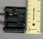
The new boards can be easily identified as they have an 'A' suffix printed on the board next to the download socket (e.g. CHI030A).

They are physically the same size as before, so can still be used in projects originally designed for the older versions.

The main updates are almost all enhancement requests from our users:
  • Labelling of i/o updated to match PICAXE-18M2 i/o labelling system
  • Added row of pads between PICAXE and darlington buffer to allow easy access to portB pins for logic level interfacing (e.g. use with AXE033 Serial LCD).
  • Added optional pads to use a 78L05 regulator on the board if desired
  • Pull down resistors on inputs C.0 and C.1 are now fitted by default
  • Reset switch is no longer fitted by default, as not required by 18M2
  • CHI035A now uses 'logic level input' FETs with a pull-down resistor
  • Added mounting holes to assist mounting into enclosures
For more details please see the datasheets:

www.rev-ed.co.uk/docs/chi030a.pdf
www.rev-ed.co.uk/docs/chi035a.pdf
 

inglewoodpete

Senior Member
* Added row of pads between PICAXE and darlington buffer to allow easy access to portB pins for logic level interfacing (e.g. use with AXE033 Serial LCD).
To me, easy access to port B is the biggest step forward. So much a problem on the earlier versions.

Well done!
 

JonRen

New Member
Hi there, I appreciate this post was some time ago but I am currently looking at purchasing one of these project boards but would require it to be placed in an enclosure. Would anyone be able to recommend me a suitable enclosure that they may have used themselves or know to be a correct fit for this board?

Thanks!
 

Jakob2803

Senior Member
I don't have the money for a project board but thanks for posting, because I looked at the layout and got curious about what a darlington array was and now I know that it would be usable for my project. :)
 

eclectic

Moderator
Welcome to the Forum.

I've just measured a board:

62mm x 54mm x 11mm deep

Probably best to search say
Rapidonline, they have hundreds of boxes. :)

e
 

Attachments

srnet

Senior Member
Before you decide on a box, you need a full picture of what going to be connected to it, switches, LEDs, sockets etc etc.
 

Jakob2803

Senior Member
I have a small question about the darlington array, and I don't see the need for a new thread. :) What is the Com pin for, on the thing? I think is means Common.
Since the darlington array is a bunch of transistors what you need are base pins for activation, collector pins and a ground pin for the emitters. These are all there. Looking over the datasheet it seems that there is a diode with the cathode pointed towards the Com pin inside each Darlington pair. Is this some kind of over-voltage security device? :)
Here is the datasheet I am looking at:
http://www.ti.com/lit/ds/symlink/uln2803a.pdf
 

westaust55

Moderator
I have a small question about the darlington array, and I don't see the need for a new thread. What is the Com pin for, on the thing?
Yes, it is the common pin for the Output Freewheeling Diodes on each channel. See the logic diagram for the ULN2803A on page 2 of the datasheet for which you provided a link.

If an inductive load such as a relay is connected to the Darlington output, when the relay coil is de-energised the coil voltage reverses and these diodes provide a safe path for the dissipation of the energy in the coil by in effect shorting the coil/load. The "COM" terminal needs to be connected to the supply line so that they are in effect reverse polarity across the load for the diodes to protect the ULN2803 channels.

EDIT: see also http://www.datasheetcatalog.org/datasheet/motorola/ULN2804A.pdf
Note while I generally use the term "Free Wheeling Diode" another equally popular term is "Flyback Diode"

For more details on the operation of these diodes (and to save me a lot of typing) see here: http://en.wikipedia.org/wiki/Flyback_diode
 
Last edited:

Jakob2803

Senior Member
Yes, it is the common pin for the Output Freewheeling Diodes on each channel. See the logic diagram for the ULN2803A on page 2 of the datasheet for which you provided a link.

If an inductive load such as a relay is connected to the Darlington output, when the relay coil is de-energised the coil voltage reverses and these diodes provide a safe path for the dissipation of the energy in the coil by in effect shorting the coil/load. The "COM" terminal needs to be connected to the supply line so that they are in effect reverse polarity across the load for the diodes to protect the ULN2803 channels.

EDIT: see also http://www.datasheetcatalog.org/datasheet/motorola/ULN2804A.pdf
Note while I generally use the term "Free Wheeling Diode" another equally popular term is "Flyback Diode"

For more details on the operation of these diodes (and to save me a lot of typing) see here: http://en.wikipedia.org/wiki/Flyback_diode
Thank you. Ah yes I have seen those used before with relays. :D
 

AllyCat

Senior Member
Hi,

They're also often called "Commutation Diodes", but COM might just stand for "Common" (rail).

Cheers, Alan
 

JonRen

New Member
Thanks for your help, there won't be anything attached to the box itself so a standard one should suffice, thanks for the recommendation.
 

Dermotx

Member
Hi. I've looked at the schematic for this board and I don't see any 1k resistors going to the inputs of the picaxe. Picaxe Manual 3 page 26 deals with switch inputs and the diagram shows a 1k resistor connected to the input pin in addition to the 10K pulldown resistor. Is the 1K resistor not strictly necessary then?
I've seen lots of circuits on the internet without this 1k resistor.

Picaxe Manual 1 page 70 shows a switch interfacing circuit WITHOUT the 1k resistor!

Regards

Dermot
 

rossko57

Senior Member
Adding a series resistor to input pins is just idiot-proofing, minimising the risk of damage should something unexpected happen - pins can be accidentally configured as outputs in software, as well as electrical suprises on the incoming line. They are not needed for understanding in examples or expermentation. They are a good practice in practical experimental or finished circuits. They are rarely _necessary_ but usually a good idea.
 

Dermotx

Member
Adding a series resistor to input pins is just idiot-proofing, minimising the risk of damage should something unexpected happen - pins can be accidentally configured as outputs in software, as well as electrical suprises on the incoming line. They are not needed for understanding in examples or expermentation. They are a good practice in practical experimental or finished circuits. They are rarely _necessary_ but usually a good idea.
OK. Thanks for clearing that up.

Regards

Dermot
 

ZOR

Senior Member
Nice to use before darlington, board much better. However why on this and other boards there are no mounting holes?
 
Top