Tutorial on using SRLatch as a 555 timer

BillBWann

Member
I've recently used the SRLatch feature on the 08M2 for the first time to latch some fast pulses and it worked well. I see in the description of the SRLatch command that "The SR latch also contains an internal clock source. This means the SR latch can be optionally configured to act like a ‘555 timer’."

Is there a tutorial on how & why this can be done? I've tried searching but haven't been successful.

Similarly, I'd be interested in reading a tutorial or other people's experience in using the comparator. I see that kranenborg (http://www.picaxeforum.co.uk/showthread.php?21422-M2-chips-Can-Serial-Out-pin-be-overridden-to-become-a-DAC-input/page2&highlight=srlatch+08M2) has used this feature in one of his programs (which I didn't fully understand) on an 08M2. Would this be recommended?

I don't have an immediate need for either of these features but I thought it would be useful to know more about them.

Thanks

Bill
 

westaust55

Moderator
Last edited:

AllyCat

Senior Member
Hi Bill,

No, I'm not aware of any tutorial either, but had been considering starting a similar thread. However, as far as I can see, the "timer" period can be ONLY 1, 2, 4, 8 .... 128 cycles of the PIC instruction clock (nominally 1 MHz) so the maximum possible period is quite short. In particular, even the longest period is less than the execution time of a single PICaxe instruction, which IMHO severely limits its usefulness.

Yes, it happens that I'm currently working on a project which uses a comparator in one of the M2 devices, so it's certainly possible. But you do have to be prepared to "get your hands (very) dirty" understanding and working with (many of) the raw PIC's Special Function Registers. :(

Cheers, Alan.
 

Goeytex

Senior Member
I would also like to know how to use the SRLATCH feature to act as a 555 timer. Since Rev-ED made the 555 claim / comment in the Manual, perhaps an official explanation and some sample code is in order.

My assumption was that the latch would be set by a short pulse on SRI and then reset by the clock after a period of time determined by the clock setting. (Monostable Timer). However this configuration only results in garbage out on the SRQ pin. (Using an 08M2)
 

Dippy

Moderator
I would imagine the "claim" is derived from Microchip's headline "SR Latch (555 Timer) module ....."

There is some mention on Microchip's forum, but I suspect a cut'n'paste solution will require some searching.
And the Data Sheet gives some clues about combining the on-board logic/comparators to achieve it.
Come on Hippy get breadboarding, it's too hot to mow the lawn :)
 

kranenborg

Senior Member
Hi Bill,

Indeed I have been using the comparator in the 08M2 successfully, and as Allycat hints this requires some real time investment in reading the Microchip datasheets of the microcontrollers (but it is certainly worth it!). I have documented a bit more in an earlier project on the use of the two comparators of the 18M2, which started me to look at the 08M2 as well:
http://www.picaxeforum.co.uk/showthread.php?17654-Use-of-Comparators-in-the-PICAXE-18M2

The actual comparator functionality differs per chip type, also note that the 08M2 has only one comparator and has slightly different input connection possibilities as compared to the 18M2. I am at work now but I could try later to document a bit more on the combi of latch and comparator as used in my application that you refer to (Capturing fast events with programmable noise-canceling). This application uses the latch simply as a memory bit which triggers an interrupt so that the event can be dealt with (and the interrupt routine then resets the latch again). This setup is used since the interrupt implementation on the picaxe may not be fast enough to capture the fast event itself

/Jurjen
http://www.kranenborg.org/electronics
 

BillBWann

Member
Thanks Jurjen for your reply. I’ve had another look at your 08M2 setup using both the comparator and the SRLatch(your #13 and #14 of http://www.picaxeforum.co.uk/showthread.php?21422-M2-chips-Can-Serial-Out-pin-be-overridden-to-become-a-DAC-input/page2&highlight=srlatch+08m2) and I was confused as to why you used the comparator and then set the DAC at level 31. It seems to me that if you set it that high, then you may as well go straight to the SRLatch. So if I understand you correctly, this is only test code and in your real situation, your program would adjust the DAC downwards. Thanks for presenting this as a programmable comparator on an 08M2 connected to the SRLatch seems like a very useful thing to have.

Also on this and in light of Hippy’s #19 of http://www.picaxeforum.co.uk/showthread.php?17052-Interrupt-on-18M2/page2&highlight=srlatch+08m2 (where he uses C.2 simultaneously as an output for the latch and an input for polling), I would think that you could you do away with your connection between C.2 & C.1 and setup the interrupt on C.2 directly. Do you agree or are you aware of a problem with doing that? I have used a slight variant of Hippy’s code example and setup the interrupt on pinC.2 directly and it all seemed to work perfectly.

Thanks everyone else for your replies.

Bill
 

BillBWann

Member
Hi Jurjen again.

I've just had another look at your 08M2 program and see that I was a bit hasty in my previous reply. If I have it correct now, the counter will only increment if the input pulse drops a bit below Vcc/2 and adjusting the DAC level will mean that the input pulse needs to be even lower still. I also assume that when I read the datasheet further, I should be able to adjust the comparator config registers to make the counter trigger on positive pulses of varying voltage levels.

Is there a reason why you used the 22k voltage divider on C.1 and not just simply connect it to Vcc and then set the DAC to say 15?

Thanks again.

Bill
 

BillBWann

Member
I’ve now had a chance to read the pic datasheet (thanks Westaust55 for the references) – at least the part relevant to this discussion and had a play with changing various configurations. This is the first time I’ve looked at the raw pic datasheet and it wasn’t quite as scary as I had imagined. I think I’ve now got a reasonably good understanding of how & why Jurjen did what he did. This combination of DAC, comparator & latch makes for a very flexible pulse detection circuit so thanks again Jurjen for bringing this find to our attention; its so much easier to play around with code that already works than to start out from scratch.

That still leaves my original request for info on the SRLatch/555 comment in the manual. Could Hippy or Technical please either confirm or deny Alan’s comment at #3 that the picaxe is too slow to make use of this feature; in which case, maybe you should consider removing that comment from the manual.

Thanks again everyone. This has all been most instructive.
 

Technical

Technical Support
Staff member
That still leaves my original request for info on the SRLatch/555 comment in the manual. Could Hippy or Technical please either confirm or deny Alan’s comment at #3 that the picaxe is too slow to make use of this feature; in which case, maybe you should consider removing that comment from the manual.
The PICAXE firmware provides full control of the SRlatch - all functionality of the Microchip SRlatch silicon is available.
The "555 timer" reference is originally their phrase, not ours, e.g. page 7 of ww1.microchip.com/downloads/en/DeviceDoc/41565b.pdf
Of Course you may need to use external timing devices (e.g. a cap) as with a 555 timer to duplicate all functionality.

In fact the PICAXE 'srlatch' command is really just a set of peeksfr commands to the appropriate registers (and SRSET, SRRESET commands act as you would expect to trigger the set/reset bits). So anything you can do with the Microchip PIC SRLATCH you can do with PICAXE. However you do need to understand the functionality to use it to its full extent, so we'll look into a better tutorial.
 

AllyCat

Senior Member
Hi,

Yes, I largely agree with technical, but I think a key phrase in the Microchip document is that the SR Latch is "internally tied to comparator". However, the comparators are NOT directly supported by PICaxe Basic on M2 devices (but can be accessed via SFR commands).

The "on chip" hardware basically provides 8 (rather short) "preset" time delays, and you could indeed add an external capacitor to create a "timing ramp" (like a 555 timer) for longer delays. That is sometimes possible using just the threshold of a "digital" input (often with Schmitt input levels), but generally far better done with a comparator input. Also, if you want to use both external "Set" and "Reset" inputs, then again you need to employ a comparator input as the flip-flop has only one (selectable) input pin.

My comment previously that I didn't consider the delay very useful with a PICaxe, was because the maximum internal delay is 128 "machine cycles". Now, a reasonable amount of processing can be done in machine code (or assembler) in that time, but a PICaxe cannot execute even a single instruction in that period (so a few "dirty tricks" that I had in mind, for measuring time delays, can't work).

Cheers, Alan.
 

BillBWann

Member
I probably didn’t express myself very well in my previous #9 question. Thanks to Kranenborg & reading the pic 08m2 datasheet, I think I now have a reasonable understanding of how the SRLatch can work with the DAC & comparator to significantly improve the Picaxe’s ability to catch & process fast external analogue & digital pulses of various types.

What I can’t see at the moment is any practical picaxe use of the clock input or external capacitor connection (mentioned by Technical) to the SRLatch. Can anyone suggest any practical real life situations where making use of these facilities would be useful in a picaxe program?

Thanks
 

hippy

Technical Support
Staff member
Microchip describe the SR Latch in these terms -

■ Do anything you can do with a 555 timer
■ Amplitude Shift Keying (ASK)
■ Waveform/Pulse Generators
■ Switching Power Supplies Controller
■ Digital Controlled Voltage Controlled Oscillators
■ Oscillators
■ AC Lamp Dimmer
■ PWM Motor Control
■ Tone Generators
■ Phase Comparators

from: http://ww1.microchip.com/downloads/en/DeviceDoc/41565b.pdf

I think the problem is not so much how it is useful but how that usefulness is to be achieved, knowing how the SR latch is to be used for those purposes and what any complete circuit would be.

Microchip don't seem to have many examples of using the SR latch but they do show how it can be used as an oscillator and as an oscillator as a part of a capacitive touch sensing system -

http://ww1.microchip.com/downloads/en/AppNotes/01101a.pdf
www.cytron.com.my/usr_attachment/mTouch_Introduction.pdf‎
 

AllyCat

Senior Member
■ Do anything you can do with a 555 timer
Except perhaps operate directly from a 15 volt supply rail and sink a 200mA pulse. :) And a 555 is probably far cheaper than a PICaxe.

But seriously, the SR flip-flop may be useful for mopping up messy litle hardware functions (such as pulse-stretching) and just a few days ago I suggested its use as a phase comparator for ultrasonic frequencies (in #7 here).

Cheers, Alan.
 

Goeytex

Senior Member
I can see quite a few possible uses. However, suggesting the possibilities doesn't help very much without practical examples.
 

Goeytex

Senior Member
This thread motivated me to messed about with the SR Latch and Comparators internal to a Picaxe. After a bit of trial and error I came up with this working example. While not specifically related to a common 555 Timer application (A 555 timer CAN be used as a SR Latch) it does provide some working code that others can try.

As the magnet passes Hall 1, comp1 sets the SR Latch, then as it passes Hall 2 comp2 resets the SRlatch. The SNRQ output of the Latch ties directly to Pulsin Pin C.3. Pulsin reads the time for 1/4 revolution of the wheel.

A practical use could be for a Tachometer, or for measuring the velocity of an object passing 2 sensors. Using the Picaxe SR Latch and Comparators eliminates the need for an external Latch / flip-flop.

Code:
[COLOR="#008000"]'====================
'SRLATCH DEMO CODE
'====================[/COLOR]

#Picaxe 20X2
#No_Data
#No_Table 
#Com 2
#Terminal 9600
Pause 100

Low C.4  [COLOR="#008000"]'Enable SNRQ Pin  (This is a MUST) [/COLOR]

COMPSETUP %0010001111,%10010000 [COLOR="#008000"]'Comp1 & 2 Enabled[/COLOR]
                               [COLOR="#008000"] 'Use Ladder - (~1/2 Vcc)    [/COLOR]   

SRLATCH %10001100,%00100001 [COLOR="#008000"]`Set on COMP1-  [/COLOR]
                           [COLOR="#008000"] 'Reset on COMP2-  [/COLOR]
do

   pulsin C.3,1,W0        [COLOR="#008000"]'SRNQ Output (C.4) ties directly to[/COLOR]
   sertxd (#w0,cr,lf)     [COLOR="#008000"]'Pulsin Pin (C.3)  [/COLOR]
   pause 1000

loop
 

Attachments

Last edited:

BillBWann

Member
Hi Goeytex,

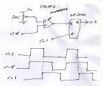
I wrote the program below a few days ago when playing around with the newly found treasures inside the 08M2 as pointed out by kranenborg here. It would work for your situation also if the pulses from the Hall effects sensor were positive. It would be possible to reconfigure the comparator to let the C.4 input trigger on a low pulse from Hall 1 but as there is only 1 comparator in the 08M2, Hall 2’s output would need to be inverted with an external transistor or something. I’ve attached a diagram showing how the comparator is set up on the 08M2 for the positive going pulses. Unfortunately, my standard of documentation is considerably less than yours.

Code:
#rem

#13 & 14 of http://www.picaxeforum.co.uk/showthread.php?21422-M2-chips-Can-Serial-Out-pin-be-overridden-to-become-a-DAC-input/page2&highlight=srlatch+08m2

Refer circuit diagram "Comparator-SRLatch....for phase shift.jpg"

The following code sets up the SRLatch on the 08M2 GP board so you can measure the phase shift delay between a leading signal on c.4 and a lag signal on c.1.  Because the SRLatch only allows one pin to be connected to it, this program connects c.1 directly to set the latch and then uses the undocumented comparator to route C.4 through to reset the latch. Note that latch is reset dominant so if both set & reset signals are present, it resets.

Pin c.4 is connected to the negative input of the comparator while the positive input is connected to the DAC output.  The DAC in turn is connected between Vcc & ground and the output is set to 2/32*Vcc. Because I want a positive input on C.4 to set the latch but its connected to the negative input of the comparator, the output of the comparator needs to be inverted.

#endrem

#picaxe-08m2
#no_data

REM SYMBOL Declarations:
REM --------------------

REM Relevant settings for DAC
SYMBOL DACCONFIG = %10000000	'DAC enabled with top set to Vcc
SYMBOL DACTESTLEVEL = 2 	'Vcc/16 = 0.3 volts

REM Relevant register addresses ansd settings for the comparator 
REM These settings imply that the comparator takes the DAC output and C.4 
REM as inputs, and the comparator output is not routed to an external pin:

SYMBOL CM1CON0 = %01010001		'Comparator Control register 0
SYMBOL CM1CON1 = %01010010		'Comparator Control register 1
SYMBOL CMOUT 	= %01010101		'Comparator Output register 

SYMBOL valCM1CON0 = %10010100		'Comparator enabled, output inverted and uses normal power
SYMBOL valCM1CON1 = %00010001		'DAC connected to pos input & C.4 connected to neg input
SYMBOL valCMOUT 	= %00000000		'Comparator Output register value

Symbol SRLatchOutput = C.2	'Connected to PulseInput
Symbol LeadingInput = C.4	'Internal pullup enabled for this test setup only
Symbol LaggingInput = C.1	'Internal pullup enabled for this test setup only
Symbol PulseInput = C.3		'Connected to SRLatchOutput so can use pulsin command

REM --------------------
REM END of SYMBOL declarations


REM Initialization:
REM --------------

REM DAC and Comparator initialization (See SYMBOL declarations).
DACSETUP DACCONFIG
DACLEVEL DACTESTLEVEL
POKESFR CMOUT, valCMOUT
POKESFR CM1CON0, valCM1CON0
POKESFR CM1CON1, valCM1CON1

REM SR-Latch configuration:
SYMBOL SRConfig1 = %10001000	'Latch enabled with Q output to C.2
SYMBOL SRConfig2 = %00011000	'Comparator connected to set input & C.1 connected to reset input

SRLATCH SRConfig1, SRConfig2
SRRESET
OUTPUT SRLatchOutput				'Needed to make c.2 an output pin (but can still be used for polled input or interrupt but not for pulsin))

REM *****
REM MAIN:
REM *****

do
pulsin PulseInput,1,w0
sertxd (#w0,cr,lf)
loop
Comparator-SRLatch Example on 08M2 for phase shift.jpg

I have tried without success to use this combination to undertake amplitude shift keying by using the clock input to provide the carrier frequency and the C.4 input to switch it on & off. The set-up is nearly exactly as for the pulse shift case above except that I’ve swapped the C.1 connection to the latch reset input over to the clock output by changing 3 lines of code in the previous program to

Code:
SYMBOL SRConfig1 = %11111000	'Latch enabled with Q output to C.2, slow clock (1kHz)
SYMBOL SRConfig2 = %00011100	'Comparator connected to set input & clock connected to reset input

SRLATCH SRConfig1, SRConfig2
My reasoning was that with C.4 high the latch would be set and the Q output would be high. When the clock input to the reset input of the latch was also high, the precedence of the reset signal would set the Q out low but it would go high again as soon as the clock pulse went low so I’d get an inverted version of the clock out on C.2. But C.2 only goes high and stays there. Can anyone see where I’m going wrong?
 

BillBWann

Member
I’ve had another look at the amplitude frequency keying problem that I reported yesterday and now find that it was working all along. The principal problem was that I was expecting the clock signal to be a square wave and the CRO I’d been using is pretty antiquated. When I attached a logic analyser to pin C.2, I see that the clock signal is a pulse about 0.2 uS wide and the clock period is exactly as expected.

I also made some typing errors in yesterday’s post when defining the configuration registers. This wasn’t the cause of my problem but for the record, it should have read:-

Code:
SYMBOL SRConfig1 = %11111000	'Latch enabled with Q output to C.2, slow clock (8kHz)
SYMBOL SRConfig2 = %00010100	'Comparator connected to set input & clock connected to reset input
I hope I haven’t wasted too much of anyone’s time on this and that my meandering progress may have been useful to someone..
 

Goeytex

Senior Member
N0 waste of time at all.

I also noticed the 250ns Clock pulse when using the 14M2. However on a 20X2 I could see no signs a SR clock signal existed, no matter the settings. So I enabled both comparators and applied a 38KHz signal to one and serout to another to make a neat little 38Khz Modulated IR transmitter. Attached is a schematic and a screen shot from the Logic Analyzer. Code is below.

Code:
[COLOR="#008000"]'===============================================
'IR Transmitter using COMP1 / COMP2 and SRLATCH
'================================================[/COLOR]

#Picaxe 20X2
#No_Data
Setfreq M8
Low b.1

COMPSETUP %0010001111,%10010000 [COLOR="#008000"]'Enable Both Comparators [/COLOR]
                                [COLOR="#008000"]'Invert Both Comparators[/COLOR]
                               [COLOR="#008000"] 'Set IVR / ladder  to 1/2 Vcc
[/COLOR]
SRLATCH %10001000,%00010010  [COLOR="#008000"] 'Enable SRLATCH and SRQ     [/COLOR]
                             [COLOR="#008000"] 'COMP1- Sets and COMP2- Resets LATCH  [/COLOR]
              
Pwmout C.5, 52, 105  [COLOR="#008000"] '38Khz  - Tie C.5 (PWM) directly to B.3[/COLOR]

[COLOR="#008000"]'Tie B.2 directly to B.4 [/COLOR]
Do

   serout B.2, N4800_8, ("Hello",cr,lf)
   pause 10

loop
 

Attachments

Last edited:

Goeytex

Senior Member
Schematic

And here is the schematic.

It may be a good idea to put a 180 ohm series resistor between the Pins that are directly tied. Also I imagine that 1200, or 2400 baud will be more reliable and give better range in a working transmitter.
 

Attachments

Top