Trouble with PWMOUT

tracecom

Senior Member
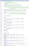
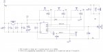
Attached is the code and the schematic for my 12V motor controller. When I press the button on C.1, the motor runs fast, and when I press the button on C.4, the motor runs slowly, and when no buttons are pressed, the motor stops. That's all good, but when I press the button on C.3, the motor makes a stuttering noise and doesn't turn. Can anyone tell me where to look for the mistake? Thanks.
 

Attachments

Last edited:

inglewoodpete

Senior Member
When using PWM, low 'on' periods may not provide sufficient energy to a) Start the motor and/or b) keep the motor running. You may be able to start the motor turning with one of the higher ratio PWM commands and, once the motor is turning, keep it running slowly with the 20% rate. You probably need to increase the PWM pulse ratio on the slower option to actually start the motor. As well, starting the motor under load often needs an initial short burst of 100%. 20% PWM does not mean 20% of full speed for the motor - it means energy going into the motor for only 20% of the time.

You've just stepped onto the steep learning curve of connecting electronics to mechanical things!
 

tracecom

Senior Member
Thanks for the response. Actually, the low speed works fine, as does the fast speed. It's the medium speed which won't turn the motor. I am truly perplexed.

Ignore this post and read post number 4.
 
Last edited:

tracecom

Senior Member
Further testing this morning has shown that the problem is connected to C.3, which will run the motor with a 999 duty cycle but not with 998 or anything less. C.1 and C.4 have not shown any problem with duty cycles down to 299 (or maybe lower.) Thanks for all input.
 
Last edited:

inglewoodpete

Senior Member
Time for some debugging.
Add #Terminal 4800 to the top of your program, along with the other directives
Add Pause 1000 as the first executable command at the top of your code (This gives the Terminal window time to open before the program starts logging immediately after downloading the program.)
Add SerTxd("$") as the second executable command (before Main: )
Add SerTxd(#pinC.1, #pinC.3, #pinC.4, CR, LF) in between Main: and the first "if" statement.
The program will run slightly slower due to the logging command but it will indicate if the program is restarting ("$") due to the motor affecting the 12v power source.
 

tracecom

Senior Member
Time for some debugging.
Add #Terminal 4800 to the top of your program, along with the other directives
Add Pause 1000 as the first executable command at the top of your code (This gives the Terminal window time to open before the program starts logging immediately after downloading the program.)
Add SerTxd("$") as the second executable command (before Main: )
Add SerTxd(#pinC.1, #pinC.3, #pinC.4, CR, LF) in between Main: and the first "if" statement.
The program will run slightly slower due to the logging command but it will indicate if the program is restarting ("$") due to the motor affecting the 12v power source.
Thanks. I will try that tonight or tomorrow and post the results.
 

tracecom

Senior Member
Time for some debugging.
Add #Terminal 4800 to the top of your program, along with the other directives
Add Pause 1000 as the first executable command at the top of your code (This gives the Terminal window time to open before the program starts logging immediately after downloading the program.)
Add SerTxd("$") as the second executable command (before Main: )
Add SerTxd(#pinC.1, #pinC.3, #pinC.4, CR, LF) in between Main: and the first "if" statement.
The program will run slightly slower due to the logging command but it will indicate if the program is restarting ("$") due to the motor affecting the 12v power source.
I cancelled an activity in order to perform the testing. I do see that the program restarts over and over while C.3 is high. No such restarts are taking place while C.1 or C.4 is high. I have a 1N4001 and .02uF cap across the motor terminals. I will do some research to see if I can find more info.
 

tracecom

Senior Member
@inglewoodpete As best I can tell, the problem was a poor solder joint on the wire connecting SW2 to pinC.3. After doing the sertxd testing you suggested, I tried that highly sophisticated test called "wiggling the wires" and found that I could move the C.3 wire one way and the problem manifested, and move it the other direction, and the problem did not manifest. Thanks for your interest and your help.

ETA: It turns out that I had to add a .1uF bypass cap near pinC.3 to completely eliminate the problem.
 
Last edited:

inglewoodpete

Senior Member
Good to that you're now on top of the problem.

Pin C.3 is a little different to the other pins on an 08M2. It does not have the internal protection diode between the pin and positive power rail pin. This is because in doubles as the Vpp pin, used to program the raw PIC. This may be why a capacitor on that pin helped stabilise the circuit's behaviour.
 
Top