Transistor Help in driving LED's

GGnz

New Member
Hi there,

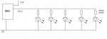
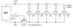
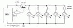
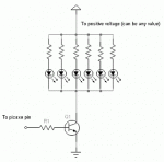
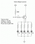
Attached is my current circuitry for an LED strobe light I am creating. I am having problems wiring in a transistor. My circuit consists off 27 LED's wired in series to the Pin 1 output with 220R resistors. I have tried wiring in NPN and PNP transistors (due to lack of current from the pin output) but cannot seem to get the LED's lighting and flashing. Can someone give me a quick run down on how transistors work? I wish to wire it into the part of the circuit between the pin output and the first LED's and have it carrying a positive current to the LED's (resistors and wiring already done etc. so no room for change). Is this possible of is there a better way of acheiving this? It seems that the diagrams I keep finding work based on a negative charge to the transistor, not a positive.

Thanks for any help you can give me :)

Cheers,
Gareth
 

Michael 2727

Senior Member
Your drawing shows the LEDs wired in parallel not series.

Look at the picaxe_manual3.pdf file, Standard Interfacing
Circuits.
You can use either the single Transistor or MOSFET options.
Note: that 27 LEDs @ 20mA each will total 540mA or
just over 1/2 an AMP.
You can supply the transistor with any voltage e.g. 5V, 12V
but make sure the current limiting resistors match and only
allow 20mA to 25mA to each LED, or 40mA in the case of
white LEDs. (Check the rating of the LEDs you are using)
 

jodicalhon

New Member
^^Wot Michael said.^^

Here are two versions, one using an NPN transistor, the other using a PNP transistor.

I have used BC337/BC327 transistors, with a 1k base resistor.

With 220 ohm resistors and a 5V supply, each LED will pass ~13.6mA, assuming a 2V drop across the (red) LEDs. Multiplied by 27 means around 370mA, which the circuit I have shown should handle fine.
 

Attachments

gengis

New Member
How transistors work is an interesting topic and one you really should read about before . . . but that won't solve your immediate problem.

The conventional way of driving the string of leds is with an NPN transistor switching to ground (emitter ground, collector to cathode of the leds) the base of the transistor would require a current limiting resistor from the picaxe to the base and turns on when the output goes high.

The resistor on the base is selected to keep the transistor "saturated," but without wasting more power than necessary or burning out the base. Transistor has a gain of 100 (for example) and your collector load is 20 ma per led times five leds (100 milliamps). Then the base requres ~1 milliamp to turn on (and extra to allow for falling gain as collector current rises, or temperature drops - gain drops) say a 1-2.2K for the example. The data sheet for the transistor you use will have graphs that show the gain available for different loads on the collector and temperatures. You design for the "worst case."

Your individual current limiting resistors for the leds would be based on how much voltage is dropped across the led (led data sheet), the supply voltage and how much current you want to run.

White leds require about 3.3 volts so may not work or work well with a 5v supply and won't work with a <3 volt supply.

The PNP variant is similar. Emitter goes to positive source, and turns on when the base is point six volts lower than the emitter - so if you want to run it from a picaxe, the picaxe has to pull high when it is off (so I added a small pull up resistor to make sure it happens)

PNP's can be turned on/off from a lower source like the picaxe when operated from a higher source, but it takes either an NPN transistor to do it, or a pair of diodes (like a signal diode in series with a zener diode). If the picaxe were driving it directly, its "high" output is only 5 volts so if the emitter is at +12 it will be turned on no matter if the picaxe is low or high.

Sorry for the crappy schematic
 

Attachments

GGnz

New Member
Still no luck. I have wired in my PNP transistors as shown in your diagrams. Testing with a multimeter shows 5V at which the datasheet says is the Emitter and Base (even when the I only have the 5V going to the Collecter or Emitter. Is it possible I have the pins on the transistor wrong (or the datasheet is wrong)? I am using a Darlington PNP 4A iC (1.5iC cont.) transistor. BD682 is the code I believe.

Oh yeah and the LED's are parallel :S
 
Last edited:

GGnz

New Member
What about a MOSFET? I also have seen in the manual you can get a transistor array also but these appear to be NPN.
 

jodicalhon

New Member
If you're using a PNP transistor, you need to have 5V on the emitter and 0V on the resistor connected to the base for the transistor to turn on. 5V on both the emitter and base will turn the transistor off.

I doubt that the datasheet is wrong. Please make sure you have the right datasheet for your transistor.

Have a look at this site for basic electronic information:
http://www.ibiblio.org/obp/electricCircuits/
 

GGnz

New Member
Yeah done that. I been using a Breadboard to test before hard soldering anything. Testing with the multimeter shows a significant voltage drop across the transistor. The Emitter reads 4.99V (same supply as Picaxe) but the collecter shows 3.6V which means the LED's are very dim with the 220ohm resistors.

What other options do I have for powering? I'm thinking relays might be an idea but I need a response time of about 40ms for a strobe, even less. The power supply I have is already 500mA so that would be more then enough.

Any ideas? I feel extremely thick but nothing I read on the net seems to be working. Could I have transistors that are too powerful?


EDIT: Upon closer research I think P-Channel MOSFET might be an idea, assuming the pin goes to the gate, 5V to the source and LEDs connected to the drain. This should allow more then enough current I think?
 
Last edited:

jodicalhon

New Member
Darlington transistors will have a larger Vce than non-darlingtons. What does your datasheet say about Vsat for the current the transistor is passing.

Pop in a BC327, as per the schematic I posted, and compare.
 

Matt_C

Member
I would go with the transistor and use the NPN transistor diag. that Flobby posted. A BC549C with a base resistor of around 1k to 2k should do the trick. It works for my 140mA fan that peaks 180mA on power up.

Just as a quick test try to bridge the transistor to make sure that you have not made a mistake and that the LED's light up.

I also think your resistors to the LED's are a bit high assuming your using standard red LED's. Try this LED resistor calculator as it also gives a nice graphical output - http://led.linear1.org/led.wiz
 

gengis

New Member
Both the darlington and standard small signal mosfet like the 2N7000, will require some voltage to turn on. The point six volts is for a standard bipolar transistor not a darlington. While transistors are current amplifying devices they also have a voltage overhead that must be met before current flows.

In the case of a bipolar silicon transistor it is point six (or so - variable with temperature).

In the case of a darlington you are hit with both a VCE sat (how low the drop across the transistor can be when driven hard) AND! a relatively high base to emitter voltage to turn it on in the first place. Both factors work against you when using low voltages.

For a typical darlington you could expect 1.5 volts drop across the transistor and require 2.0 volts to turn on.

For a mosfet 4 volts to turn on but next to nothing for current. "Logic Level" mosfets are a new breed and turn on with less voltage and still may need over 2 volts . . .

If the 3.6 volts is at the collector to ground that is working well (for a darlington it is all you should expect with 5 v in)

So your choices are get a bipolar and drive it a little more (less gain means more base current to turn on) or search around for a "botique shoppe" with some parts with fancy pedigrees and or prices that will work within your criteria.

AND I don't rember reading in the thread your voltage drop for the leds you are using- a white led will need 3.3 volts or so before it starts getting happy. Red may work at 2 volts or less. See the led datasheet.
 

BCJKiwi

Senior Member
If the effective supply voltage is just 3.6v due to drops across the Darlington array, then surely the answer is to reduce the value of the current limit resistor to improve brightness.

If you use a calculator such as the one at http://www.led.linear1.org/led.wiz and use 3.6V as the supply voltage instead of 5V then the new current limit resistor value will be much lower.

So if you want to use the Darlington (or whatever you have) and the output of that device is 3.6V then use that voltage in the calculation for limiting resistor along with the correct voltage and current values for the LED you have.
 

GGnz

New Member
Sweet will buy the Transistors shown in the diagram and hopefully this should do the job (this time). I will let you know. Maybe I shouldn't off went for the high power expensive transistors.
 
Top