That little clock that appears on screen when running a DS3232.

banda

Member
I'm working with PICAXE VSM, being a beginner in picaxe.
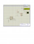
A while ago I bragged that I could rescue that lovely little time-keeper that appears with DS3232, (and DS1307).
It had disappeared, and I messed about until I made it re-appear.
Well, it's gone again. I must have pressed some signal for it to disappear again.
Fiddling with the DS3232 edit function doesn't make it re-appear for me this time.
I don't know what to do to recover it.

It's important for me to see the correct time during a project I'm attempting.
Does anyone know a (foolproof ! ) method of recovering it?
 

Dippy

Moderator
I don't have the PICAXE VSM but I have it's Mother; Proteus.

I have sometimes closed the 'oscilloscope' and it still remains 'gone' when I restart the simulator.
The way to get it back is; run the simulator, then Mouse-Right-Click on the component and on the dropdown is (sometimes) the device name e.g. "Digital Oscilloscope".
Click it and the displayed screen returns.
It may be similar for your clock screen.- this is just a guess ;)
 

jims

Senior Member
banda, I'm using this code on the attached VSM schematic. It is for the DS1307, but I would expect that your DS3232 would act the same. The clock icon appears when I run from the VSM schematic.
Code:
	'#################################################
	'#20M2 sets DS1307 and reads TOD & shows on OLED.
	'#################################################

symbol oled=C.3	' (pin 7).
  

#picaxe 20m2
setfreq m4
hi2csetup i2cmaster,%11010000,i2cslow,i2cbyte	'Set up U1 as master on i2c.
pause 1000		'Pause to initialize system

start_clock:

	serout oled,n2400,(254,1)	'Clear OLED.
 
	hi2csetup i2cmaster,%1101000,i2cslow,i2cbyte	'Set-up RTC as "slave" on i2c.
	 pause 10
	
	hi2cout 0,($00,$59,$11,$03,$25,$12,$03,$10)	'Send data to DS1307.
 	 pause 100
	 
 	hi2csetup i2cmaster,%11010000,i2cslow,i2cbyte	'Set-up RTC as "slave" on i2c.

	hi2cin 0,(b0,b1,b2,b3,b4,b5,b6,b7) 		'Read DS1307.

	bcdtoascii b1,b10,b11		'Convert minutes in (b1) to ASCii.

	bcdtoascii b2,b12,b13		'Convert hours in (b2) to ASCii.

	serout oled,n2400,(254,128,"TIME ",b12,b13,":",b10,b11) 'Show hours & minutes from DS1307.

	 pause 5000
	goto start_clock
Maybe this will help you. Jims
 

Attachments

hippy

Technical Support
Staff member
This seemed to work for me to remove and restore the clock display for a DS1307, is basically what Dippy posted above -

From the main menu of VSM ...
Select Help -> Sample Designs
Select "(Demo Version Samples)" then "PICAXE"
Open "AXE100 Datalogger.DSN"

Run the simulation ...
The "DS1307 Clock - IC2" pop-up should appear
Click the [X] close button of that ...
And it disappears.

Right click on IC2, the DS1307 at the right above the LCD display
Select the "DS1307 |>" at the bottom
Click on "Clock - IC2"
And it reappears
 

Dippy

Moderator
That's what I was badly trying to compare the oscilloscope operation with.
It's not obvious in Proteus/Isis (and I assumed VSM too) how to get things back if you close them.
 

banda

Member
Well, well, well. The things one learns when in August company.
Who would have thought of asking the system questions in the middle of a program?
Thanks to you all I can now have my little clock back whenever I want it.
I would be hopelessly lost without your help and advice.

I can't let it stop at that though.
Why is it I can't automatically initialise time from my PC?
I tick the appropriate little box, but the program restarts from the time it was closed at.
Is that not working with a DS3232 in PICAXE VSM ?
Will it work when I get on to breadboarding ?
 

DAC90

New Member
Greetings jims,
I hope you don't mind me bothering you with this question. I am trying to program a clock using the DS1307 and a 20M2. I have not been having much success in getting code to work completely with this chip. For example I entered your code above in order to test the result but get the following output TIME ??:?? I am not sure why the output is a question mark and not a number. Bear in mind I am a relative new comer so have a lot to learn. But any light you can throw on this would be much appreciated :)
many thanks
dac90
 

jims

Senior Member
DAC90...you will get that result when the Clock chip icon is excluded from the simulation. Check by doing this...right click on the clock chip icon on the VSM schematic...edit properties...uncheck the "exclude from simulation". JimS
 
Top