Synchronised PWM

inglewoodpete

Senior Member
I am working on a project where I'm driving a 3W RGB LED with 3 PWM channels. The duty of each channel will differ from the other two to give a wide range of colours.

I want to detect the PWM with another PICAXE using a band pass filter/detector front-end set at the PWM frequency. The filter is necessary to desensitise the detector to other lighting g. The filter/detector that I have developed works well when using simple Red, Green or Blue. However, the method comes unstuck with some combinations of colour and duty because the cycle start times are out of phase, leaving one or another of the LEDs 'on' throughout any PWM period.

So, to my question: is there a way of synchronising the leading edge of multiple PWM channels on a PICAXE? I have looked at hPWM but this seems to be limited to each channel having the same duty, which restricts the colour range that I can produce.

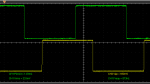
Below is a DSO screen snap of the RGB signals from a 28X2. Being only dual trace, I have triggered the oscilloscope on the red channel and the display traces the green and blue PWM signals. All three channels are currently set at 50% duty.

PWM Phases.PNG

Note: The development work that I am doing, if successful, may be used for personal financial gain.
 

hippy

Technical Support
Staff member
On the 28X2 I believe the C.1 and C.2 share the frequency counter / timer so I think they should have their rising edges synchronised. The question then is whether B.0 or B.5 can be made to use the same timer.

From a quick read of the datasheet it looks like it is possible, or that all PWM 'duty comparators' can select the same counter / timer, but it would involve determining which controls which and poking around with SFR bits.
 

inglewoodpete

Senior Member
All good suggestions. I'm trying to keep the chip count/wiring complexity down so will dig deeper into hippy's suggestion, starting with logging the PWM-related SFRs' data.

If that is unsuccessful, I'll consider bit-banged PWM using a raw PIC like a PIC12F1840. I suspect that using a PICAXE to produce bit-banged PWM would produce too much variation in PWM frequency, affecting the ability to reliably detect the PWM signal.

Unfortunately, adding a PCA9685 (great chip but a TSSOP28 package) would complicate the hand-assembly of the small run of boards proposed for the project.

Thanks for the suggestions - I'll report back in the coming days.
 

rossko57

Senior Member
Off-topic question; why detect PWM when you can have the PWM-ing Picaxe tell you what it is doing, over serial or somesuch?
 

inglewoodpete

Senior Member
Without all the details, I can understand people asking "why?" I am limited in what I can say at the moment but I'll try to provide some details.

The RGB LEDs form the transmitter part of a proximity detection system for a moving or kinetic sculpture. As objects get close to each other, the pulsing, visible LED light from an emitter gets stronger, triggering a detector in the 'receiving' object. In order to discriminate from other light sources (Eg daylight or 100 Hz from mains lights), I need all LED (RGB) elements to be 'off' at some point in each PWM cycle, so that a specific 'carrier' frequency is produced.

For sure, there are other forms of proximity sensor but I'm looking for a simple, easy-to-explain concept (I'm probably making a fist of explaining it here but I'm in a competitive situation). Hopefully, my team will win the contract and I can provide further details later.
 

Buzby

Senior Member
Another idea is to add a second, separately driven, 38KHz IR LED in the vicinity of the RGB LED. The receiver then could monitor the invisible IR level.

Or, wire the PWM outputs to three 2-input AND gates. Use an output to enable the three gates simultaneously.
 

inglewoodpete

Senior Member
Another idea is to add a second, separately driven, 38KHz IR LED in the vicinity of the RGB LED. The receiver then could monitor the invisible IR level.
I had considered 38kHz IR but I don't want to flood a public building with 38kHz IR, potentially masking legitimate IR signals.

Or, wire the PWM outputs to three 2-input AND gates. Use an output to enable the three gates simultaneously.
I'm not sure how that one would work. Gating the PWM would change the LED colour and not actually cause an alignment of the three PWM signals.

Thanks for the suggestions. I'm currently poking (actually, peeking:)) around the SFRs, seeing how Rev Ed configures the PWM when using 3 channels.
 

Buzby

Senior Member
Gating the PWM would change the LED colour and not actually cause an alignment of the three PWM signals.
If your PWM is is in the order of 100's of Hz, then simultaneously gating all channels at, say 10KHz with a 10:1 pulse, would not significantly alter the colours, but would give you a rock steady 10KHz as long as any of the PWM are on.

Given that you are in a race, you need to get something working quickly. This idea could be breadboarded in 10 minutes, and you would have an answer in 20.
 

inglewoodpete

Senior Member
If your PWM is is in the order of 100's of Hz, then simultaneously gating all channels at, say 10KHz with a 10:1 pulse, would not significantly alter the colours, but would give you a rock steady 10KHz as long as any of the PWM are on.
I hadn't thought of the gating the PWM at a high frequency (maybe not my quickest day :)). I'll give it a try. The MOSFETs might not like it, though (I'm using 300mA -1W- LEDs).

Congratulations on your upcoming 2,000th post!
 
Top