Switching positive volt

late_voyager

New Member
Hi,
as in previous posts for my project I have 12 volt (regulator) and 24 volt (battery) output on different pins on a plug 24v is then switched with the IRL 520 from picaxe command. to drive external buzzer/sensor/relay/lamp etc
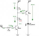
I would like to have the negative as common and one pin as 12/24v out put and switch this with picaxe..
cant get my head round positive switching..
any one have circuit ideas
thanks in advance
 

westaust55

Moderator
Can you please clarify:
1. Are you trying to switch one or both of the voltages you mention,
2. How many circuits of each voltage
3. What are the current draws (Amps/milliamperes) for each circuit
4. How many circuits will/can be on st the same time.

There are high side equivalents to the ULN2803 for up to 8 channels at the same voltage up to around 200 mA depending upon number of channels in use at one time.
For higher currents you many need to look at using discrete transistors.
 

premelec

Senior Member
PNP or PMOS transistors can be used to switch positive line.... mechanical relays still work ;-0
 

late_voyager

New Member
Can you please clarify:
1. Are you trying to switch one or both of the voltages you mention,
2. How many circuits of each voltage
3. What are the current draws (Amps/milliamperes) for each circuit
4. How many circuits will/can be on st the same time.

There are high side equivalents to the ULN2803 for up to 8 channels at the same voltage up to around 200 mA depending upon number of channels in use at one time.
For higher currents you many need to look at using discrete transistors.
Hi, I am only using one voltage at a time. like plugging in a 12v bulb or a 24v bulb. but use picaxe command to switch between 12/24v
only 1 circuit for 12 and 1 for 24
current is less than 500ma ( Car type relay, prox sensor,)
 

westaust55

Moderator
The following schematic (snapped form another forum) using an NPN and PNP transistor as typical can be driven by a PICAXE to turn on a light bulb.
You may need to add a resistor between the transistor and LED/bulb if the voltage greater than the power source.
Resistor R2 will likely need to be higher ohms value depending on the actual supply voltage.


High Side Switch.jpg

If your load is the 500 mA mentioned then you will need to allow for around 50 mA still to put Q2 into saturation to minimise volt drop and heating of the transistor.
 
Top