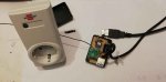
Challenge: Wirelessly switch an electrical plugin socket via a USB interface.
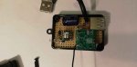
Parts: old PICAXE-08M,
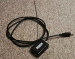
Cheap 433Mhz Modul,
Brennenstuhl Wireless Socket,
some Small parts.
Implementation: The code consists of a total of 24 bits + 1 sync bit at the end
A bit consists of an 0 and 1 sequence (Manchester)
0 bit 430 us on and 1150 us off (approx. 1/3)
1 bit 1150us on and 430 us off (approx. 3/1)
Examples:
Switch coding Brennenstuhl Wireless Socket
has two DIP switches:
1122334455 AABBCCDDxxofon
where switch on corresponds to 00 respectively
and switch off corresponds to 01.
Example:
Examples:
11 22 33 44 55 AA BB CC DD xx of on
01 01 01 00 01 00 01 01 01 01 00 01 A On
01 01 01 00 01 00 01 01 01 01 01 00 A Off
01 01 01 00 01 01 00 01 01 01 00 01 B On
01 01 01 00 01 01 00 01 01 01 01 00 B Off
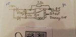
The PIC-AXE 08M sends the 20 * ON signal as soon as it receives power via the USB interface. This is sent via a Cheap 433Mhz Modul to the radio socket and it switches on.
As soon as the USB interface is deactivated (e.g. TV goes off), this is noticed via PIN 4 (IN3) over the loop. The PIC-AXE 08M is still powered by the 2200uF capacitor. This is enough to send the OFF signal several times until the capacitor is empty. The radio socket goes out.
I connected the data line of the USB interface to a USB socket, so that the USB interface remains fully usable.
To send the suitable signal I used PULSOUT. But I didn't find a suitable command to realize the pauses in between. The 08M does not know a PAUSEUS command yet. Therefore I took PULSOUT and put it on pin 5 (Out2), which I don't use.
Parts: old PICAXE-08M,
Cheap 433Mhz Modul,
Brennenstuhl Wireless Socket,
some Small parts.
Implementation: The code consists of a total of 24 bits + 1 sync bit at the end
A bit consists of an 0 and 1 sequence (Manchester)
0 bit 430 us on and 1150 us off (approx. 1/3)
1 bit 1150us on and 430 us off (approx. 3/1)
Examples:
Code:
 +-+   +-+   +---+ +-+   +-+
 | |   | |   |   | | |   | |
 | |   | |   |   | | |   | |
-+ +---+ +---+   +-+ +---+ +----

 |  0  |  0  |  1  |  0  |sync
Switch coding Brennenstuhl Wireless Socket
has two DIP switches:
1122334455 AABBCCDDxxofon
where switch on corresponds to 00 respectively
and switch off corresponds to 01.
Example:
Code:
Switch       Buttons
      o        o
o o o   o    o   o o
1 2 3 4 5 A B C D11 22 33 44 55 AA BB CC DD xx of on
01 01 01 00 01 00 01 01 01 01 00 01 A On
01 01 01 00 01 00 01 01 01 01 01 00 A Off
01 01 01 00 01 01 00 01 01 01 00 01 B On
01 01 01 00 01 01 00 01 01 01 01 00 B Off
The PIC-AXE 08M sends the 20 * ON signal as soon as it receives power via the USB interface. This is sent via a Cheap 433Mhz Modul to the radio socket and it switches on.
As soon as the USB interface is deactivated (e.g. TV goes off), this is noticed via PIN 4 (IN3) over the loop. The PIC-AXE 08M is still powered by the 2200uF capacitor. This is enough to send the OFF signal several times until the capacitor is empty. The radio socket goes out.
I connected the data line of the USB interface to a USB socket, so that the USB interface remains fully usable.
To send the suitable signal I used PULSOUT. But I didn't find a suitable command to realize the pauses in between. The 08M does not know a PAUSEUS command yet. Therefore I took PULSOUT and put it on pin 5 (Out2), which I don't use.
Code:
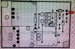
;#picaxe 08m
;#######################################################################
;#
;# Anschlüsse am PICAXE 08M:
;#                              +  2200uF
;#     USB Power +5V ----+->--+--||------------------------+--- 0V
;#                       |    |      +---U---+             |
;#                       |    +-- + o|1     8|o 0V---------+
;#                       |       0V o|2     7|o            |
;#                       |       0V o|3     6|o 1 RFCOUT   |
;#                       +->--+---3 o|4     5|o 2 Dummy    |
;#                            |      +-------+             |
;#                            +------------------R47k------+
;
; Der Code besteht aus insgesamt 24 bits + 1 Sync-Bit am Ende
; Ein bit besteht aus einer an und aus Folge
; 0 bit 430 us an und 1150 us aus (ca. 1/3)
; 1 bit 1150us an und 430 us aus (ca. 3/1)

; Schaltercodierung brennenstuhl
;
; 1122334455AABBCCDDxxofon
; wobei Schalter auf on bzw. Taste jeweils 00 entspricht
; und Schalter auf off bzw. nicht gewählte Taste 01 entspricht
;
; Beispiele:
; 11 22 33 44 55 AA BB CC DD xx of on
; 00 01 00 01 01 00 01 01 01 01 00 01 A Ein
; 00 01 00 01 01 00 01 01 01 01 01 00 A Aus
; 00 01 00 01 01 01 00 01 01 01 00 01 B Ein
; 00 01 00 01 01 01 00 01 01 01 01 00 B Aus

; Hier:
;
;Example:
;Switch     Buttons
;    o        o
;o o   o o  o   o o
;1 2 3 4 5  A B C D

; 01 01 01 00 01 01 00 01 01 01 00 01 =  B On
; 01 01 01 00 01 01 00 01 01 01 00 00 =  B Off


symbol RFCOUT = 1
symbol RFD = 2
symbol H0 = 43
symbol L0 = 18
symbol H1 = 112

pause 300

; On
for b0 = 1 to 20
pulsout RFCOUT,H0        ;0
pulsout RFD,L0           ;
pulsout RFCOUT,H1        ;1

pulsout RFCOUT,H0        ;0
pulsout RFD,L0           ;
pulsout RFCOUT,H1        ;1

pulsout RFCOUT,H0        ;0
pulsout RFD,L0
pulsout RFCOUT,H1        ;1

pulsout RFCOUT,H0        ;0
pulsout RFD,L0
pulsout RFCOUT,H0        ;0
pulsout RFD,L0

pulsout RFCOUT,H0        ;0
pulsout RFD,L0
pulsout RFCOUT,H1        ;1

pulsout RFCOUT,H0        ;0
pulsout RFD,L0
pulsout RFCOUT,H1        ;1

pulsout RFCOUT,H0        ;0
pulsout RFD,L0
pulsout RFCOUT,H0        ;0
pulsout RFD,L0

pulsout RFCOUT,H0        ;0
pulsout RFD,L0
pulsout RFCOUT,H1        ;1

pulsout RFCOUT,H0        ;0
pulsout RFD,L0
pulsout RFCOUT,H1        ;1

pulsout RFCOUT,H0        ;0
pulsout RFD,L0
pulsout RFCOUT,H1        ;1

pulsout RFCOUT,H0        ;0
pulsout RFD,L0
pulsout RFCOUT,H0        ;0
pulsout RFD,L0

pulsout RFCOUT,H0        ;0
pulsout RFD,L0
pulsout RFCOUT,H1        ;1

pulsout RFCOUT,H0       ; sync Bit
pause 9
next b0

;*******************************************************************
; Beim Strom weg wird der VCC Eingang noch durch einen Kondensator gepuffert
; An pin3 liegt aber die direkte Spannung an und geht vorher auf 0
; dann wird mit der Restkapazität des Kondensator das aus Signal gesendet.

SCHLEIFE:
if pin3 = 1 then SCHLEIFE


;Off

for b0 = 1 to 50
pulsout RFCOUT,H0         ;0
pulsout RFD,L0
pulsout RFCOUT,H1         ;1

pulsout RFCOUT,H0         ;0
pulsout RFD,L0
pulsout RFCOUT,H1         ;1

pulsout RFCOUT,H0         ;0
pulsout RFD,L0
pulsout RFCOUT,H1         ;1

pulsout RFCOUT,H0         ;0
pulsout RFD,L0
pulsout RFCOUT,H0         ;0
pulsout RFD,L0

pulsout RFCOUT,H0         ;0
pulsout RFD,L0
pulsout RFCOUT,H1         ;1

pulsout RFCOUT,H0         ;0
pulsout RFD,L0
pulsout RFCOUT,H1         ;1

pulsout RFCOUT,H0         ;0
pulsout RFD,L0
pulsout RFCOUT,H0         ;0
pulsout RFD,L0

pulsout RFCOUT,H0         ;0
pulsout RFD,L0
pulsout RFCOUT,H1         ;1

pulsout RFCOUT,H0         ;0
pulsout RFD,L0
pulsout RFCOUT,H1         ;1

pulsout RFCOUT,H0         ;0
pulsout RFD,L0
pulsout RFCOUT,H1         ;1

pulsout RFCOUT,H0         ;0
pulsout RFD,L0
pulsout RFCOUT,H1         ;1

pulsout RFCOUT,H0         ;0
pulsout RFD,L0
pulsout RFCOUT,H0         ;0
pulsout RFD,L0

pulsout RFCOUT,H0
pause 9
next b0

stop
Attachments
-
 21.3 KB Views: 12
 -
 21.5 KB Views: 12
 -
 21 KB Views: 12
 -
 43.7 KB Views: 11
 -
 41.2 KB Views: 10