Submarine camera for very deep water photography.

hax

New Member
So to preface, in 2006 I launched two high altitude weather balloons equipped with cameras, Picaxe, GPS and UHF radios. I tracked them from Melbourne, Victoria to the NSW border. It was a great little project, and a few people got involved along the way.

Now I am thinking of doing some deep sea underwater photography, in the small chance I can find some creatures that humans have not discovered yet.

The idea is to build a device that can withstand the pressure of the ocean at 10Km under water. This is around 15000 PSI or about one tonne per square cm.

To keep things simple, the device won't have any propulsion at all. It will be dropped from a ship, at which point it will sink to the sea floor, take photos of moving objects for about a month or so, then automatically resurface and hopefully be retrieved. The idea is that there will be a camera, LEDs, and some sort of motion detection to only capture the events that may be interesting. This would involve some sort of optical motion sensor, as using sonar, or IR sensors is not suitable at these depths. I think that a low power LED could be turned on to attract any creatures, and some high power LEDs could be turned on while filming or taking photos.

So far, I think the best option is to have the craft comprise of three main sections, all joined with a galvanised chain. The top section will be for flotation, consisting of an incompressible, lighter than water, substance such as motor oil or kerosene. (fully sealed of course)

The middle section will be the camera, beacon, LEDs and electronics, and the bottom section will be some sort of weight such as a large stone.

I propose that after a certain elapsed time, the stone will disconnect from the electronics enclosure, and the electronics, and float will resurface and be rescued. The stone will remain at the bottom of the sea floor.


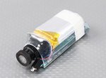
I have two questions that I would like input on. One is how to do the motion capture. I was thinking of using an optical mouse with a suitable lens for crude vision detection. Comments? Anyone done this with a picaxe?

The other question is how to release the weight. I was thinking of using a seatbelt pretensioner that pulls a pin out and releases the chain. Not sure how these go at high pressures tho. I could have it inside its own oil bath, but again, not sure if it will work at high pressure.
The other idea I had was to use two dissimilar metals for the chain, so that galvanic corrosion would eat away at the link, and sooner or later, would release the camera and float. The disadvantage of this being that you could not time it to release at an exact moment, hence the recovery of the camera would be less certain.

Appreciate any other ideas. I'm just at the planning phase at the moment.
 

Hemi345

Senior Member
I have never lived near the ocean so I'm not sure how quickly things collect gunk from the water. But I was thinking an LDR (or three for redundancy) could be placed on the top of the float so that when your device surfaced, the detected light would trigger powering up a beacon to use for recovery.
 

hax

New Member
That's a good idea. Also, I found some infrared proximity sensors from Sharp that look like they may work through a thick sheet of plastic. I could maybe roll my own with an IR pickup and IR LED.
 

Adamey

Senior Member
Interesting project. I've always been fascinated by submarines and the problems with keeping things safe inside a pressure vessel yet having them interact with devices outside.

For the weight just make up a quick release hook as used on some cranes (smaller version, of course). Use a solenoid to pop the release. A solenoid should work under any pressure - the only thing you need to worry about is corrosion so make sure it's sealed. Although I think a galvanic corrosion backup would also be required in case of electrical problems. But instead of using that on the actual load bearing chain use it on a small pin with a spring to pop the quick release. Probably much more predictable since only a small piece needs to corrode instead of a large chain.
 

boriz

Senior Member
Great project. Love it.

Galvanic techniques might be a problem. Many aquatic species are sensitive to electric fields and it may function as a deterrent. You'll need to consult an ocean biologist I guess.

Coupling a release mechanism could be tricky. How do you get the mechanical impulse from inside your envelope to outside? Any electrical wiring will just leak.

I saw neat 'door-holder-open' type device in the local cinema. It had a permanent magnet on the wall behind the door, and a metal projection on the door. When the door was opened far enough, the projection stuck to the magnet, holding the door open. The neat bit was how you released it. There was a small button next to the magnet, which when pressed energized a solenoid coil just behind the magnet with the opposite EM force, briefly cancelling the permanent magnet's effect and releasing the door. It was a very strong magnet, and I'm sure it took a good whack of power, but it only needed to be applied briefly.
 

Jeremy Harris

Senior Member
Fascinating project, sounds great fun.

Around 25 years ago I designed and built a system that was designed to stay on the sea bed for up to 30 days, then blow an inflation bag and surface, bringing a recovery line up with it. This was for shallow water (~40m maximum) and worked OK. I used a real time clock chip with a programmable alarm output as the recovery timer and programmed this before deployment with a small microcontroller hand held unit (that used a Scorpion K4, if anyone's old enough to remember them!). The RTC alarm output operated a solenoid water valve (OK at these modest pressures) which let water in to a standard lifejacket water activated CO2 inflation valve, that then blew the floatation bag. This took a light line to the surface that was then used to run a big recovery line down to a snap hook arrangement on the sea bed device (which was a ~1 tonne anti-ship acoustic mine!).

For this job I think the same sort of recovery timer could be used. Using an RTC like this gives an independent, fairly simple, way of ensuring timed release, with a very low power consumption. This could be independently powered for redundancy, too, and would only need a small lithium primary battery. The weight release could be via a mechanical servo hook, one where a tiny (external) lever allows the hook to open by using the force of the ballast weight as a servo. A coil encapsulated next to the actuating lever could be used to provide the small force needed to move the lever. Think of the sort of sear mechanism you have on the trigger of a gun, one where the force on the firing pin comes from energy stored in a spring from either cocking or gas recoil.

I look forward to hearing more. Dealing with the cold may be one of the biggest problems, I think, as at this sort of depth the batteries are going to be working at around freezing point for long periods of time.
 

MFB

Senior Member
Some years ago I was involved in developing oceanographic instrumentation and it really was fascinating and challenging work. Two items of standard equipment being used back then were a simple core sampler and the other a more complicated photographic probe. The sampler was just a steel tube that embedded its self in the sea floor and then released ballast to float back to the surface with a sample. No electronics was required. However, the photographic probe was much more along the lines of your proposed instrument. After making a much softer landing than the sampler it used the same mechanical approach for dropping ballast and re-surfacing. Electronics was only used to activate the camera and lights.

My point is that you may be able to keep the basic vehicle quite simple/reliable by using these well proven techniques and leave more development time for the motion/camera electronics.
 

bfgstew

Senior Member
What an intresting project, look forward to reading how you get on with it and seeing the results. My hat goes off to you and wish you all the best.

Stewart
 

Steve2381

Senior Member
Great project idea. I have built an RC submarine and had enough issues getting that watertight at 2 metres!

As mentioned.... I personally think the cold will be the main issue (closely followed by pressure!). All components are going to have to be tested pretty thoroughly.

I think the release mechanism is going to be a case of keeping it super simple. What that would be however.... not sure. Any kind of solenoid at those pressures surely is going to need a wallop of juice to release it.

Interesting info here:

http://en.wikipedia.org/wiki/Acoustic_release

They show a fuse link which seems quite simple.

http://en.wikipedia.org/wiki/File:Fusible_Link_Release_Mechanism_ARC1.jpg
 
Just a quick thought. I use a magnetic base on my lathe to check centre height. never really thought how it works but I guess one magnet inside another, so when the inside one is moved sideways it changes the polarity or something. you could operate the sliding centre with a small gas cylinder i.e. a soda syphon sparklette and a small solenoid valve, little battery power required, no holes in your submarine!!!!. Given the level of precision required for engineering the vessel you could dispense with the magnet and just make a pneumatic bolt to release the anchor chain serious precision to avoid leaks etc. BUT the new species you are looking for might attach itself to your anchor, pity to loose it! so use the gas cylinder (soda stream size) to inflate a flotation device, easier engineering (only one hole in your submarine but no moving parts!) bring the anchor up as well, clear conscience, no rubbish left behind not even a rock!!.
look forward to hearing more on a fascinating project.
best wishes
D
 

Jeremy Harris

Senior Member
I was thinking more along the lines of a simple disc hook QR mechanism, with a simple encapsulated coil to pull the release pin out. This is a very big version of this type of QR hook: http://quickreleasehooks.com/towing/

These things are fairly easy to make with hand tools, I think.

I've tried using fusible links underwater but it isn't that easy. They need a heck of a lot of power, because the sea water takes away the heat from the fuse wire. To get the prototype one I made working, I had to cover the wire with insulation, just to allow it to get hot enough to fuse. We had more luck with melting fishing line using a hot wire. This still needed insulation, but we could get away with much finer wire as all it was doing was melting through a bit of nylon line. Depending on the weight of the ballast, a simple loop of nylon fishing line holding the weight directly and fed through a blob of silicone sealant that's insulating a thin wire wrapped around the line might work OK. Easy enough to test it in the freezer at home to see how reliable it is.
 

rossko57

Senior Member
I'm sure the OP realises this is rather specialist engineering.
Example
Pressure at depth ~ 15,000 psi
"Soda stream" bottle ~ 1,500 psi
Rating of bottle fittings ~ 3,000 psi
Inflation style mechanisms would be a problem here.

If a 'balloon' were inflated at depth it'd have to be rather stretchy to expand a few hundred times as it rose; it might be possible to use a bladder in a box to prevent that problem - but then you might just as well have a standard sub style ballast tank, with all the complication of holes in hull either way.

EDIT: thinking more on flotation, a 'parachute' will do - excess air just spills out during ascent. A 20,000 psi bottle is realistic, even if not likely to be found in the hardware store. A risk of loss due to predator attack though?

Magnetic anchor-drop does seem easier to implement. Some kind of "glass" will be needed if the camera/lights are to be any use? which could provide the antimagnetic pathway for a mechanism. I'm guessing the hull will need to be high quality carbon steel for this job.

You'd probably want to have some kind of relief valving to avoid bringing any 15,000 psi pressurised container back to the surface by accident - operator hazard!
 
Last edited:

Buzby

Senior Member
... This is around 15000 PSI or about one tonne per square cm. ...
Wow !. That's some pressure !.

Have you got access to machinery to simulate this kind of environment ?

Before working out how to get it back, I'd be more concerned about how to make it survive 30 seconds at that depth, never mind 30 days.

Good Luck !
 

rq3

Senior Member
FWIW, WWII era mines released their anchors after a salt tablet dissolved. Food for thought?
 

Jeremy Harris

Senior Member
Not really that hard to make something withstand that sort of pressure, as it's much easier to deal with compressive stress than tensile stress. The key thing is to prevent crippling failure, but using a short cylindrical vessel with thick end plates would be a pretty straightforward thing to analyse in structural terms, and probably the easiest shape to make, as well.

Even big acrylic bubbles can go to surprising depths, because, like many materials, acrylic has a remarkable high compressive strength when evenly loaded. I have a couple of acrylic lenses in old deep sea camera housings that I think were rated to around 3000m or so. They are about 3" diameter and maybe 1/2" thick, but domed to spread the stress out evenly. The seals are simple O rings in compression, working on a chamfered face, so the greater the pressure, the better the seal. The chamfer allows the stresses to flow evenly from the edge of the acrylic to the alloy housing (which is also pretty thick). Not good enough for this project, but as these were commercial deep dive systems, expected to work for years at that working depth on submersibles, they might not be far off from what's needed.
 

Ravenous

Member
Perhaps the interior of the sphere can be prevented from filling up with seawater by... pre-filling it with an incompressible fluid. A non-conductive fluid such as an oil... Have you seen these nutters who run their PC in oil baths and so on to improve cooling? Something like that.

(I gather there are proper non-conductive liquids that circuits can just be immersed in, though I gather they're specialist/expensive/polluting.)

Just an idea...
 

MFB

Senior Member
The photographic probe that I mentioned used an air filed glass sphere (about 25cm) to pull it back to the surface when the ballast was disconnected. This sphere contained a battery an xenon flash tube for location. All drops were made at night and the recover beacon cold be seen from the crows nest from several miles. No need for fancy GPS repeaters! I'm sure the details of the mechanical ballast release and flotation sphere can still be found by searching oceanographic publications.
 

Marcwolf

Senior Member
An interesting project. I have been thinking re the release mechanism and how you might handle it. Ideally there should be no electrical or mechanical linkage between then inside of your pressure vessel and the external as any entryway is a weak point. However lets consider the solenoid and how it works. You could have a coil of wire at the bottom of the pressure vessel that when activated uses it's magnetic field to pull the release pin. The advantage being that because the pin and release mechanism is under the same force everywhere then the power to move it is no greater than the force required at the surface. And as the magnetic field is only needed for release the coil does not need to be energized all of the time. Alternatively the base and the pressure vessel can he held together by magnetic force and the pulse from the coil reverses the magnetism of pressure vessel and do magnetically repels it from the base. Just some idea's
 

hax

New Member
All very good ideas.

I'll try using a copper coil to "de-energise" two strong magnets. I was thinking of using a spark plug as the cable feed-through between the pressure vessel and the release mechanism. Spark plugs seem to be well made, but I am not sure if even they can cope with the pressures we are talking here.
 

boriz

Senior Member
I'm picturing something like this: http://i.imgur.com/1pMyCAk.jpg

Solves a lot of problems if it's solid. The battery can be charged inductively and the controller can be communicated with optically using IR commands.

You'll need to destroy it to get your pictures and data out though.

On motion detection. Sea floor currents will swill silt and debris around. And any nearby plant life will also wave about. Just something to consider.
 

boriz

Senior Member
Skywave or bounce propagation can be used instead of a specifically timed release. Once at the surface, a short burst burst every couple of hours (say), with even bursts sending Longitude and odd burst sending Latitude. Something like that. Shouldn't take much power, and you'll be able to pick it up from the comfort of your own home (maybe).

Knowing the exact moment of release is an advantage. But the advantage diminishes with drifting due to currents. It's not going to sink straight down, and it's not going to float straight up. It might pop up 50 miles from the drop point. And at sea level, that's quite a bit beyond the horizon.
 

Jeremy Harris

Senior Member
There are certainly some very interesting challenges here. My experience with underwater instrumentation, video etc was all with stuff that only went to three or four hundred metres at most, but many of the issues will probably be similar. Overall I learned the hard way that the simpler you can make something that has to work in this environment the more likely it is to work. I reckon about 90% of our failures were down to overly complex, or just over-engineered, bits of kit.

One thought I've just had is related to position finding and communications. I doubt that an external antenna, either GPS or comms, would be that easy to fit, both because the lead-throughs would be difficult to seal (and create a stress raiser) and because I doubt that a ceramic GPS antenna would survive the pressure. This suggests that putting the antennas inside the pressure hull might be sensible, but then you have the problem of RF attenuation, even if you machine the pressure hull from engineering plastic. It might work, but I think some experimentation first would be a good idea.

Finally, one configuration that we found worked very well for floating recovery devices (we even adopted it for recovering trials torpedoes) was to arrange for them to float like a spar buoy, vertically, with a fair bit out of the water. If your device is cylindrical, then having the fixed ballast at one end, and the floatation and release ballast at the other end, would mean that when release it would float vertically. If the antennas are at the buoyant end then this gives them a better chance of getting clear of the water and getting a signal.
 

MFB

Senior Member
Your antenna advise fits in well with my drift buoy experience. These were made from a modified aluminium beer keg with a weight hanging underneath to keep them upright. Three 1-metre tubes held the receiver and transmitter antennae, plus a xenon recover beacon above the mean water line. Surprisingly, even with waves frequently breaking over buoy it was possible to get good but intermittent reception from hill top receiving stations.

Returning to the ballast-drop and recovery techniques, I don't see much point in reinventing the wheel when passive and reliable means to achieve this seem to have been perfected by oceanographic researchers decades ago. Just a case of searching out the information.
 

dennis

Member
There may be some useful information to be found from a web search of the cable laying industry. They still have to use repeaters which work at great depth, need seals, and are expected to last a long time. My father worked as a surgeon on a cable laying ship just after the war and described the difficulty of dealing with repeaters that had failed and let in seawater. Back at surface level there is an immense pressure and a lot of stored energy to dissipate. With this scenario its not just compressive forces that the housing needs to withstand.
I wonder if its possible to place all components in a flexible plastic bag filled with glycerine or some other non conducting clear fluid and let them be exposed to the pressure.
 

srnet

Senior Member
For anyone interested in real long distance GPS tracking, I have just been writing the code (which works) that uses a 28X2 and RFM22 radio (100mW) to transmit the GPS location data as FSK RTTY, This can be picked up on a Funcube dongle or other comms receiver. A £6 DVB TV dongle and low noise UHF amp is almost as good.

Line of sight range for tracking ought to be in excess of 1000km.
 

MFB

Senior Member
That does sound interesting. Do you have a write-up yet that we can access? I'm currently evaluating an Iridium based Rockblock board for global telemetry coverage but it will demand a lot more current than your approach.
 

srnet

Senior Member
Yes;

http://www.picaxeforum.co.uk/showthread.php?21822-PICAXE-in-Space&p=228836&viewfull=1#post228836

What I was evaluating was given that you are using an RFM22, how best to maximize your chances of retrieving data back from long distances, 1000km plus. Whilst the 40km LOS range of RFM22 packets on 1/4 wave antennas is not bad at all, adding an LNA in front of it 'only' improves reception by 12db, add a high gain yagi and still reception from a 750km orbit is highly marginal.

The FSK RTTY shows a benefit of some 26dB over RFM22 data packets, so add a yagi and LNA and things are really looking up.

The RFM22 puts out an FM Morse beacon too, and based on the same power the FSK RTTY is retrieved at the point where the FM Morse is barely audible. From the 40km tests I know that the Morse beacon can be heard at that distance when TX power is a mere 1mW, so upping the power to 100mW is clearly going to extend the reach of the FSK RTTY considerably.

The satellite will be using 100baud FSK RTTY, although if you change the PICAXE frequency to M16, you get 200baud.

The RFM22 does show frequency drift of up to 200hz in the few seconds after the TX is turned on, which obviously affects the RTTY tones, however FLDIGI tracks the changes well enough. Reducing TX power reduces the problem.
 
Top