Stripboards / veroboards

Mycroft2152

Senior Member
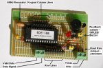
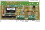
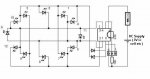
My latest PICAXE / DIPTRACE project is interfacing with Veecad, a stripboard layout program.

Veecad requires a separate schematic editor to generate netlists. Then matches the components frrom Veecad's footprint library and does the stripboard layout.

It's a pretty clever program and under $25US.

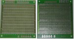
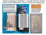
I'm curious how many forum members use the stripboarding techinique. So chime in if you do!

I don't expect many responses from US forum members, as stripboardss are pretty much unheard of in the US and are difficult to buy.

Thanks,

Myc
 
I'm from the US, and I frequently construct stripboard circuits. I currently use "Lochmaster" for laying out stripbaord circuits, but I'll check out VeeCad.

Ron
 

Dippy

Moderator
I don't . Haven't for years and years. Breadboard to PCB. I have nothing against stripboard. I used to use it when I was a lad, but it is limiting when phyical layouts become significant. Whilst pcbs can take a little more time I found I made less errors. Maybe I'm clumsy. Hores for Courses.
 

BCJKiwi

Senior Member
Use stripboard for anything small.

Issue with Diptrace to VeeCad from an initial look seems to be the need to conform to VeeCads pin numbering system.
All attempts to import a netlist from Dipace failed with errors. It appears that it was because Diptrace used a, b, etc on components where VeeCad requires 1, 2 etc or did I miss something?

I was only testing the free version of both programs.
 
Last edited:

Mycroft2152

Senior Member
Use stripboard for anything small.

Issue with Diptrace to VeeCad from an initial look seems to be the need to conform to VeeCads pin numbering system.
All attempts to import a netlist from Dipace failed with errors. It appears that it was because Diptrace used a, b, etc on components where VeeCad requires 1, 2 etc or did I miss something?
You hit the nail on the head!

The problems with using netlists beteen programs are all due to inconsistant naming of pins and footprints (patterns in DIPTRACE) and the availiblilty of matching footprints in the library. There are no standard names, each program is unique.

DIPTRACE uses letters for some pin names. this usually happens with diodes and LEDs (ell eee dee). where A and K are used***.

I had a similar problem with VSM that also threw in a couple of pluses and minuses as well.

The easiest way to fix a DIPTRACE library is to export it in the DIPTRACE ACSII format, use a text editor to replace the A and K with 1 and 2, and then import it back into the DIPTRACE Library file. This does work as I've done it.


On the Veecad side, there needs to be a library with footprints that have the same names as the components in DIPTRACE. As it stands now, there
Veecad library is very limited, but I understand there is work being done by the developer to build a library databese.

My current project is to create a DIPTRACE library and Veecad library useful for the boards I make. Similar to the one I did for VSM.

It would be very handy to have a single library that could be used in all three programs.

Being abole to draw the scheamiotc once and then generate eiother a pcb layout, or a strip board layout would be great.

I'll be posting the libraries as I get them done. both here and on the DIPTRACE Yahoo group.

Myc

One of these days, I'll have to set up my own website. any suggestions / reccomendations?

*** Added: Going though the standard DIPTRACE libraries, transistors use B, C, E as pin names and need to be changed
 
Last edited:

rbright

Member
Thanks for the intro to VeeCAD

Thanks Mycroft2152 I've just licenced VSM and are an old veroboard (stripboard) user for years. I'm follow your posts with interest because like others I find PCBs a bit of a pain.
This is all causing me to get an understanding about netlists & their compatability.

Looking forward to your future contributions.

Cheers
 

BCJKiwi

Senior Member
@Myc,
Thanks for that.

Perhaps VeeCad should be encouraged to have another look at their seeming philosophic objection to anything but numbers.
For those not working on this stuff constantly, and those just dabbling in a hobby mode, the letters mean something where the numbers do not. I know a strict numbering style (as advocated by VeeCad) helps but is not intuitive in the way that letters are (is there any intuitive linkage between BCE and 123 ? - perhaps BCE == 312!).

Will await your admirable work on a common library set and then have another look.

Many thanks in anticipation.
 

westaust55

Moderator
Stripboards / veroboards & proto-baords

Years ago I did design my own PCB’s by hand for up to A4 size for computers and microcontrollers of the day.

Now for the smaller one-off’s that I experiment in my PICAXE world, while I have occasionally used vero-board where I have a need for some more continuous/longer tracks but have been using more of the Dick Smith Fibre-glass Proto-boards (cat H5613). Have a small breadboard for early stages of new experiments.

These are 95mm x 85mm silk screened single-sided printed circuit board with etched copper pads. There are +ve and –ve busses and strips of three holes which prove to be convenient without the need for drilling to break tracks as required with standard vero-board product.

For small projects involving say a 24 pin keyboard encoder, or a couple of PCF8574 8-bit IO expanders, each with some extra resistors, plugs and sockets etc, I have generally found I can cut these proto-boards in half and use one half of each module I build up for my PICAXE. The boards have relatively clear area on two opposing sides with pre-drilled mounting holes which allow me to mount the finished module in a plastic box with some 6mm long stand-offs.
 

Attachments

Last edited:

manuka

Senior Member
I gave up on Vero board decades back, & now only recommend it for trivial use. For many projects you can't beat an initial solderless breadboard refinement, then a "paint by number" lift over to equivalent soldered tracks. Here in NZ the so called Kiwi Patch board developed by Andrew "Brightspark" has been a real winner, and at ~US$2 highly cost effective. For some years I've used the DSE H5605., but this is more costly & being Paxolin it looks pretty school boyish compared with the fi-glass Kiwi patches.

IMHO taming circuits is often taxing enough without having to rethink ones neat working breadboard over to a soldered Vero layout,then perhaps re-rethink again to the PCB. Do you Vero fans have nothing better to do!?

Of course such a final PCB version (that's IF required for mass production- often it's NOT) needs a PCB CAD package waved over it. There are so many of these that I hesitate to mention my pets for fear of re-igniting a flame war...
 

Attachments

Last edited:

hippy

Technical Support
Staff member
IMHO taming circuits is often taxing enough without having to rethink ones neat working breadboard over to a soldered Vero layout
I don't think I've ever had a neat breadboard. That's probably because I consider bread-boarding to be entirely transient in nature, mainly for testing and proving things I've not put on vero-board yet.

Most of my design is on paper then straight to vero-board.
 

westaust55

Moderator
The Kiwi Patch board is obviously a clone of a breadboard layout which, as you say, makes it easy to copy a circuit from breadboard to permanent circuit.

The Dick Smith Proto-boards (cat H5613) I use are, as I previously mentioned, also Fibre-glass and I cut them in half. They only have 3 holes per group instead of 5 used on the Kiwi Patch board but I have in general found this works well, though occasional an extra row of holes would be good (but can get around this). Typicaly I can use say a resistor direct from an IC leg to the next inline group of holes, then on to a transistor or in-line socket so a signal is often completely in a straight line out form the IC leg.

Agree that sourcing boards in this way is not the most economical, works out typically at AUD$3/module, but suits me as I can drop into a Dick Smith store on way from office to Train Station on way home each evening.

Couple of photo's to hand: one is for my keypad encoder (first module I built) and second is for 74HC595 based serial shift register to drive 8 x LED's plus transistor for 9th LED (keypad shift indication). As my boards are mounted inside plastic boxes, the keypads, LED’s, sensors, etc are mounted away from the board hence I usually have some sockets for headers to connect from boards to keypads, LED, etc.

Do you Vero fans have nothing better to do!?
With some (okay many) years of experience, I find no problems translating from one physical arrangement to another. I do recognise that some people (not having a go at anyone on this forum – just an observation from my workplace and interaction with tradespersons over many years) do not always have the ability for envisaging spacial layouts in their mind.

Quite a few of my circuits are straight to solder board without the breadboard stage.


For the newer/younger electronics enthusiasts (and maybe some vintage ones as well), the Kiwi Patch board approach certainly can be a great advantage.
 

Attachments

Last edited:

inglewoodpete

Senior Member
That's probably because I consider bread-boarding to be entirely transient in nature, mainly for testing and proving things I've not put on vero-board yet.
Thats because Stan takes photos for his family album;)

I'm with you on this one hippy. However, I do a PCB design if I have a need to make up several boards. Veroboards take additional time to wire up and debug in my experience.
 

Dippy

Moderator
Well a lot of it is personal preference.

For prototyping I use breadboard to test individual parts of a larger circuit. Then when happy I draw it on a piece of paper with a pencil. I then transfer to CAD and build up the whole circuit from the tested sub-circuits. But I've been 'at it' so long now that in many cases I know a design method will work or not without breadboard. And I keep the sub-circuits as Macros on the PC to be pic'n'mixed / cut'n'pasted as required - tricky with Veroboard.

When I was a boy and only making small circuits veroboard was fine, but when you have >X components and >Y pins/legs then Veroboard is a pain. Direct to PCB is now the only choice for me esp as some components are s/mount only.
Being able to adjust the geometry of PCB to suit an enclosure is a bonus even if you're not intending to make more than one.
Doing a large circuit on veroboard is somewhere between lunacy and showing off, or simply proving a point to the youngsters. And I maintain (and cannot be persuaded otherwise) that PCBs are less prone to error.

My attitude might be slightly different if I had to do my etching in my Mum's kitchen sink however!!

I am actually compiling all Stan's breadboard photos to design some wallpaper which I shall export to NZ. It's for kids bedrooms and they can press a button on one wall and a load of LEDs without resistors go phut on another wall.
 

manuka

Senior Member
Dippy - you're too kind, but I'm only a beginner in this game compared with the minimalism of Andrew. See the likes of his approaches with some Kiwi 10 year olds on "45 minute proto" => http://picasaweb.google.com/picaxe/45MinuteProto, beside which you'll no doubt consider mine pretty rudimentary. Naturally 45 mins of hands on electronics any other way would have been near impossible with such juniors.

And never mind juniors - I well recall a 18 yo. student (not mine) spending ~20 hours trying to tame a directly Vero boarded 555/NTC multivibrator. Yes-his soldering was pretty volcanic,as numerous dead bug 555s testified...

For my part as an educator,I've spent >30 years stressing to Y1 tertiary electronics students that neat breadboard layouts really take no longer overall than impossible to debug "rats nests". Some of the pre micro results they've then been (ahem-) "persuaded" to produce- discretes/op. amps/logic/555s/RF etc- have wiring that almost looks as if it's painted on. Naturally- best of all- circuits have usually then WORKED & can be understood. In recent years we've taken a digital pix to go with their lab. report, as boards are usually stripped straight after a practical session.

Unlike most hobbyists, such students are being trained to produce work to a standard others can (later) follow under pressure. You only need to inspect the wiring layout in a ship/aircraft/power plant/military radio to know how crucial this approach can be. Yes-I practice what I preach on this, & have long been a neat wiring fanatic on any circuitry-even as a pre school 4 year old with D cells/torch bulbs/ electromags etc!

This must make my zillioneth post on the subject, & I hereby cease further comment. Stan
 

Attachments

Last edited:

Dippy

Moderator
Haha. Don't get me wrong, I'm a firm supporter of breadboarding with plug-in stuff. And it's nice to see a circuit from scratch like that FM transmitter you posted.

But when I keep seeing posts where a total newbie cannot get his/her first PICAXE download working on breadboard then I cringe. I still think that a newbie, unsupervised and in the privacy of his bedroom, should buy the cheapest project board available just to get the ball rolling. I started off with plenty of mistakes too and still make mistakes. The only differnce is that now I can fix them and refrain from posting them all over the Forum.

And I, too, have finished on this subject..... maybe.
 

Mycroft2152

Senior Member
Hippy. Dippy et al,

There are many techniques to 'wire up" a circuit. I've used most of them over the years.

There is no "best" way to wire up circuits. Everyone has their favorite technique, based on their level of experience, tools available, neatness, and pocketbook.

Just as there is no best way to draw up a schematic. Paper and pencil, Windows Paint, generic CAD, and specialized pcb CAD programs all work.

I am in favor of the breadboard for initial design, but for a permanent circuit, it's either a stripboard, veroboard or pcb. Stripboards are great for simple circuits, but a pcb layout allows you to make copies very easily.

Unless you are set up to etch and drill pcbs, hard wiring is the fastest way to get a board made.

My latest DIPTRACE project was to create a tool for those people using stripboards. I am a beleiver in the old saying; "use the correct tool for the job".

Myc

"toolmaker'

Note: I think the "Kiwiboard" is a great design and appropriate for the age group / education market using it.
 

Dippy

Moderator
Absolutely, that's why I keep saying "Horses For Courses" - it's a multi-interpretable-multi-subjectivitisationable-all-purpose saying that means the same and more. It also rhymes and is shorter.

"Each to Their Own" is another nice saying when you've given up trying to explain the benefits of one technique over another - usually to someone who is "stuck in their ways" and/or "blinkered" and, on some occasions, "correct".
 

westaust55

Moderator
In this day and age, we are generally into stripboard, verboard, proto boards and specificallly designed PCB's etc . . .

In 45+ years of hobby electronics I have used tag strips, verboard, proto boards and project designed PCB's but have managed to bypass wirewrap. I thought it gone out of use years ago

In reading the May 2008 edition of Circuit Cellars magazine (page 34) I was happy :) to see exactly the same fibreglass protoboard I have mentioned earlier in this thread in use. This article was a project that gained 3rd place in the Microchip 16-bit Embedded Control Design Contest.


But today on reading the June 2008 edition of Circuit Cellars (page 21) I was somewhat taken back to read the following:
The Spa interface unit is wire wrapped on a small protoboard. . . . .
And this project gained 1st place in the Microchip 16-bit Embedded Control Design Contest. Mind you, the main board does look like a specifically designed PCB.


In a thread or somewhere etc, I recently saw the line:
wire wrapping is knitting for engineers
So all I can say is each to his own
 
Last edited:

Mycroft2152

Senior Member
Westy,

I forgot about wirewrapping :)

It was a good technique for its time and made making "repairs" a lot easier that unsoldering the fine magnet wire.

I even had a powered wirewrapping tool!

I still use wire wraping pins and sockets to connect things to a breadboard.

Myc
 
Top