ashawthing
New Member
Just made a small circuit to interface an SRF05 using an 08M. The idea is that the program reads the length of the output pulse from the sensor (which will be between 100uS and 30mS). This is then compared to a value from "readadc", the voltage is controlled by a variable resistor placed across the 5V supply.
The output from the circuit is simply a 1 or 0 depending on which value is greater. However I'm having trouble getting the circuit to function as I intend. I think I may be doing somthing slightly wrong in the calculations. I cant seem to get the full range of the sensor. I have tried adjusting the numbers a bit but below is about the best I can get.
The closest I can get the trigger distance to the sensor is about 20cm but then as i increase the variable resistor the trigger distance very rapidly reaches the maximum distance the sensor can recognise (about 4m). I would like a steady increase from minimum to maximum over the full travel of the variable resistor.
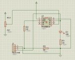
I have attached a circuit diagram and code. In the circuit diagram, on the 08M pin 3 is used as a trigger, it will be connected to a seperate circuit. Pin's 4 and 6 are input and output pin's for the SRF05 sensor.
Any help with the code would be greatly appreciated.
Another problem I am having is with programming the chip. I am not able to program the 08M on this board, the editor gives me an error saying the chip is not powered, then list a few other possibilies. Am able to program it fine on a separate board.
The output from the circuit is simply a 1 or 0 depending on which value is greater. However I'm having trouble getting the circuit to function as I intend. I think I may be doing somthing slightly wrong in the calculations. I cant seem to get the full range of the sensor. I have tried adjusting the numbers a bit but below is about the best I can get.
The closest I can get the trigger distance to the sensor is about 20cm but then as i increase the variable resistor the trigger distance very rapidly reaches the maximum distance the sensor can recognise (about 4m). I would like a steady increase from minimum to maximum over the full travel of the variable resistor.
I have attached a circuit diagram and code. In the circuit diagram, on the 08M pin 3 is used as a trigger, it will be connected to a seperate circuit. Pin's 4 and 6 are input and output pin's for the SRF05 sensor.
Any help with the code would be greatly appreciated.
Another problem I am having is with programming the chip. I am not able to program the 08M on this board, the editor gives me an error saying the chip is not powered, then list a few other possibilies. Am able to program it fine on a separate board.
Attachments
-
645 bytes Views: 33
-
 49 KB Views: 112