Some way to drive WS2812 LED string?

premelec

Senior Member
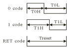
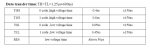
It appears that the frequency required to drive this one wire RGB chip may be too high for PICAXE to retrieve data and make up drive pulses though I'm not too clear on just what is necessary from the data sheet [other than zeros are short pwm and ones are long pwm pulse]. It did occur to me that perhaps one could make up a fake MP3 file which would have the required pulse characteristics and trigger playing that to the WS2812 but I have not a clue how one would do that... Has anyone successfully driven this chip with a PICAXE? Which chip? [I looked in this forum but found no conclusive answer..] Thanks for any help or telling me it can only be done with external components... :)
 

AllyCat

Senior Member
Hi,

IMHO, it's not possible to drive those LEDs (directly) from a PICaxe, nor use a MP3 decoder. It needs a micro (e.g. a "raw" PIC) using Assembler or a Compiled language.

The data sheet appears to specify a minimum data rate of 400k bits/second (i.e. pulses in the hundreds of nanoseconds region). That's way above the capability of PICaxe's interpreted code. Equally, MP3 is designed to encode repetitive audio waveforms (i.e. up to ~20 kHz) and the data waveform is likely to be non-repetitive and >> 20 kHz.

The only way you might do it (with a PICaxe) is with an external (24+ bits) shift register. The PICaxe would clock it slowly whilst writing bits into it (either singly or perhaps a parallel byte at a time). Then (somehow) gate a high frequency clock signal to shift out the data into the LEDs.

Cheers, Alan.
 

premelec

Senior Member
Thanks AC... I notice there are units [Ebay] that will read a FAT SD card and execute the control to the chips... I wasn't wanting to get that complicated! I'd thought of shift registers but for more than one lamp quite a large register is needed... Perhaps I'll try a semi-random 555 running on clipped noise into one of these and see what happens... :)
 

grim_reaper

Senior Member
Premelec,

I've been looking at driving WS2812B RGB strings - mainly because they seem to be the dirt cheap toy of choice with the young'uns at the moment - and was wondering if you got anywhere with the points in this thread?

Thanks.
 

PADJ

Member
IMHO, it's not possible to drive those LEDs (directly) from a PICaxe, nor use a MP3 decoder. It needs a micro (e.g. a "raw" PIC) using Assembler or a Compiled language.
I have looked into driving these LEDs, and concur. There are several excellent libraries for other micros.
 

premelec

Senior Member
I have been working with a unit; http://www.nledshop.com/pixelmini/ - which is driven by a 14M2. The designer of this unit has been experimenting with higher capacity than original and I have a test unit that will drive my 60 WS2812 pixel strip from him. I've tried some direct drive from the 14M2 to a WS2801 32 pixel strip and not got very far for unknown reasons - all the pixels light but not as I want... The NL unit is basically a buffer taking the data in at various baud rates and then sending a fast data stream out to the WS2812 strip....

BTW The strobe rate of the WS2812 is a bit annoying to me [ca 400Hz] so I'm looking into other units...
 
Last edited:

grim_reaper

Senior Member
Nice little product there, but at $25.55 (including shipping to the UK) it's a bit out of the price range I was looking for (I'm building a new kitchen so need to make about 20 light controllers... pushing $400 just to interface PICAXEs to LEDs is too much!)

The premise is good though. I'm looking at using a simple PIC interface to try and do the same thing.
 

PADJ

Member
Nice little product there, but at $25.55 (including shipping to the UK) it's a bit out of the price range I was looking for (I'm building a new kitchen so need to make about 20 light controllers... )
How many LEDs are you using? Each controller should easily handle 150+ LEDS - maybe a lot more.
 

techElder

Well-known member
Remember when kitchens only had one light bulb in the center of the room; sometimes hanging from the electric cord that powered it? ;)

No fun at all!
 

premelec

Senior Member
LED prospects

@grim_reaper - The 14M2 has 4 pwmouts available and could read pot inputs if you want to dim a bunch of LEDs using MOSFETs and DC power supply. Personally I just walk around with a 3 LED head light - there's light everywhere I look!
 

eggdweather

Senior Member
Looks like the X-parts can definitely drive the WS2812 on the SPI bus, for example using : spifast (clock freq / 4) (= 1MHz with 4MHz resonator)
Description:
The hpisetup command sets the microcontroller's hardware pins to SPI mode. This command setups the microcontroller for SPI transmission via the microcontroller's SPI hardware pins. This method is faster and more code efficient than using the 'bit-banged' spiout (shiftout) command. When connecting SPI devices (e.g. EEPROM) remember that the data-in (SDI) of the EEPROM connects to the data-out (SDO) of the PICAXE, and vice versa.

Applies To:20X2, 28X1, 28X2, 40X1, 40X2- See more at: http://www.picaxe.com/BASIC-Commands/Advanced-IO-Interfacing/hspisetup/#sthash.tnoDxLd1.dpuf
 

grim_reaper

Senior Member
How many LEDs are you using? Each controller should easily handle 150+ LEDS - maybe a lot more.
It's still in the 'pre-design phase' (or the I'm not sure what I want yet phase) but the initial idea was under-cupboard and plinth lights. The plinth is one long run, so that could be done with one 3 or 4 metre strip, but there are going to be 4 sets of wall cupboards, so that's already 5 controllers :(

Remember when kitchens only had one light bulb in the center of the room; sometimes hanging from the electric cord that powered it? ;)

No fun at all!
Still got a dull kitchen with a single central light - albeit replaced with a cluster thing some years ago - hence building a new one!

OT - I'd be interested in learning more. The Pi seems pretty quick to me, and I use interpreted APL.
I'm torn with this issue too; as you both say, the Pi has many examples of controlling RGB strips, but also many reports of the OS interrupting the sequencing. I've checked into costs of Arduino and Pi, and compared to the £2 for a 14M2 I don't think either are worth learning (for me).
But if the Pi can do it, why can't a PICAXE? Did anyone get SPI minus the CLK output working down to 300ns pulses?!?!

@grim_reaper - The 14M2 has 4 pwmouts available and could read pot inputs if you want to dim a bunch of LEDs using MOSFETs and DC power supply. Personally I just walk around with a 3 LED head light - there's light everywhere I look!
I have a pile of 14M2's - they have become my favourites - and you're absolutely right. I designed a 08M2 circuit with single pulse output (before I realised I couldn't clock it fast enough) and a pot for the overall brightness, with the RGB setting being sent to the chip via serial. Having 3 pots so the family can choose R, G and B levels themselves would be good (with a software/remote override obviously, so I'm not stumbling into the kitchen to a 5% red light!).
If you can convince my wife to wear a 3 LED head light all evening in order to save electricity costs, I'll buy you all the beer you can drink!
 

PADJ

Member
It's still in the 'pre-design phase' (or the I'm not sure what I want yet phase) but the initial idea was under-cupboard and plinth lights. The plinth is one long run, so that could be done with one 3 or 4 metre strip, but there are going to be 4 sets of wall cupboards, so that's already 5 controllers :(
A question to ask yourself (or the 'boss') is whether you need to address the LEDs individually for some funfair style animated display, or can you group the LEDs by strip and have a single mood control for each groups brightness and color?

Also be aware that the strips do age quite rapidly (months) with significant color shifts. Google for examples and videos.

IMHO we're a bit early in product development to use in 'adults' living space.
 

PADJ

Member
Looks like the X-parts can definitely drive the WS2812 on the SPI bus, for example using : spifast (clock freq / 4) (= 1MHz with 4MHz resonator)
I think you're jumping to conclusions rather too quickly, this is not an SPI device.

Reread the WS2812 spec carefully, and then perhaps youll see the difficulty of generating 1.25uS pulses with the required mark/space ratios, and meeting the rest of the inter/intra bit timing requirements.
 

premelec

Senior Member
PADJ is correct - the ones & zeros in the data stream are discerned by a mark / space ratio in a certain clock period... it is unfortunate for easy driving. :-(

I'm looking into the LPD8806 chip - seems to be SPI and down to very low clock frequency as well as having high pwm rates for less obvious strobing... Anyone experienced with this chip?
 
Last edited:

AllyCat

Senior Member
Hi,

I think the idea is that you convert a "0" to 1000 and "1" to 1110 (or it might be vice versa, I don't have the datasheet to hand) and then transmit the bits via the SPI data line at 4 MHz. The resulting 250 : 750 ns and 750 : 250 ns pulses seem to be just about within the required specification.

Typically, you'd use a lookup (table) for each pair of bits to produce one byte, thus 12 bytes for each 24 bit data block. You'll have to use an X2 (which is why I didn't consider it in my earlier post) because the bit-banging code for M2s won't be fast enough.

Cheers, Alan.
 

PADJ

Member
I think the idea is that you convert a "0" to 1000 and "1" to 1110 ....
Two things -
The resulting datastream does not quite meet the spec. In practice the first chip in the stream will decode and swallow the first 24 bits quite reliably, but may not be able to reclock the rest of the stream thru to its output port.
Or it may fail further down the strip.

Secondly the SPI block needs to be fed a byte of data every 2uS. Any gap in the bitstream will impact the reclocking even if the bits are within spec. I'm not familiar enough with the X2 to know if this is a problem.
 

eggdweather

Senior Member
I think you're jumping to conclusions rather too quickly, this is not an SPI device.

Reread the WS2812 spec carefully, and then perhaps youll see the difficulty of generating 1.25uS pulses with the required mark/space ratios, and meeting the rest of the inter/intra bit timing requirements.
1. Well there might be a difference between theory and practice: https://www.youtube.com/watch?v=wnb5RMwzyts because it is being done!
2. Extract from the RPi method: 'Connect the serial in of the WS2812 to the MOSI pin. Configure the SPI interface for 2.4MHz. Then send an SPI packet: a bunch of zeroes (*) (reset) and then you encode: 0x1 0y1 0z1 .... the xyz are the bits you try to send, and the 0.1 (*) are the "protocol bits" that the WS2812 wants for synchronization.'
3. Extract from JEELabs: 'JeeLabs is using the SPI bus on the LPC810 to clock out data at the rate required by the LEDs. The only hardware required is a small LED to drop the voltage from 5V to 3.3V and a decoupling capacitor. Yes, you could easily get away with this as a one-component build.'
I'm concluding that although not strictly an SPI device for that model number (unlike the 2801), it can indeed be driven by the SPI bus.
 

PADJ

Member
Looks like the X-parts can definitely drive the WS2812 on the SPI bus, for example using : spifast (clock freq / 4) (= 1MHz with 4MHz resonator)

I'm concluding that although not strictly an SPI device for that model number (unlike the 2801), it can indeed be driven by the SPI bus.
Indeed it can - it's easy for the Pi and LPC810, both 32bit machines running at 700Mhz and 60Mhz.
 

eggdweather

Senior Member
Well if I were to try it, I'd turn up the PICAXE to 8Mhz or even 64MHz to get a really fast SPI bus that will be well within the WS2812 timing requirement and sending the data is relatively straightforward with the PICAXE command, as is sending a regular sync dataset.
 

PADJ

Member
Well if I were to try it, I'd turn up the PICAXE to 8Mhz or even 64MHz to get a really fast SPI bus that will be well within the WS2812 timing requirement and sending the data is relatively straightforward with the PICAXE command, as is sending a regular sync dataset.
Well try it with a strip of 100 LEDs, post your code, and give us the results. I appreciate you got your first picaxe as a Xmas gift, and as a newbie it all looks easy to you, but you have a lot to learn.
 
Last edited:

grim_reaper

Senior Member
I was thinking of giving it at least a few attempts with a 20X2 at 64MHz.. but unfortunately I don't have a desk, kitchen table or any electricity in my workshop for another few months!
All of the ideas given above are worth investigating - even if just to record here that they don't work for whatever reason.
 

premelec

Senior Member
I've just been calculating and loading into RAM and then accessing with BPTR for more speed - updates take a while... [3 bytes per PIXEL]
 

Technical

Technical Support
Staff member
Well if I were to try it, I'd turn up the PICAXE to 8Mhz or even 64MHz to get a really fast SPI bus that will be well within the WS2812 timing requirement and sending the data is relatively straightforward with the PICAXE command, as is sending a regular sync dataset.
In theory:

1) A 4MHZ SPI signal produces data bits of length 0.25us. 4MHz SPI is possible with 64MHz clock and / 16
2) WS2812B requires bit length of 1.25us
3) Therefore a WS2812B bit = 5 SPI bits
4) WS2812B bit = 1 can be faked as SPI 11100 (0.75 on, 0.50 off)
WS2812B bit = 0 can be faked as SPI 11000 (0.50 on, 0.75 off)
These figures are within spec for both WS2812 (6 pin LED)
and WS2812B (4 pin LED)
5) Each RGB LED requires 24 bits = 24 x 5 / 8 = 15 SPI bytes
6) SPI bytes need to be back-to-back without any inter-byte gap for this to work.

And this is where the PICAXE can't go quick enough, there will be a small gap between each byte as the next byte is retrieved from memory. This will corrupt the timing.

If hard coded in assembler this would work, but not with the current PICAXE.
We've added it to the wish list as a desired new firmware command for the future.
 

premelec

Senior Member
@Technical - that would be good and looks a bit difficult as there are so many LED drivers materializing- The WS2812 strobe rate is annoying. I haven't got a LPD8806 strip yet but that looks to be much better.... being able to put out long uninterrupted bit streams should suit a lot of different units - good luck...
 

Buzby

Senior Member
Off the wall idea No.27,

ws2812b_Timing.png

Looking at that timing diagram, I can't see why T1H and T0H can't be extended indefinitely.

The idle state between frames must keep DI high, otherwise the chip will reset, so the state of the very first bit must be determined by the length of TxL alone.

As long as the TxH is at least 0.35uS it shouldn't matter how long TxH actually is, because it is the length of the next TxL that determines the bit 1 or 0.

If this is the case then there is no problem with a PICAXE taking a while to load the next byte to the SPI, as long as the line is held high during this time.

I've not got a WS2812, so I can't try this for real.

What does the panel think ?
 

Buzby

Senior Member
Hi PADJ,

It all depends on exactly how the chip works.

It might measure the time of the High as well as the Low, but why ?.

The chip really only needs to sample at a fixed time after a falling edge to determine if the bit is a 1 or a 0, so the 1.25uS overall time might represent the maximum speed it can run at, but not a specific requirement.

Does anyone know what happens to the chip if DI is held high ?.

Cheers,

Buzby
 

stan74

Senior Member
Ive got a RPi 3 and Python is slow to control the IO pins.The hardware pwm can be as low as 1 Hz but it's not stable.if you scope it you see it drifts,frequency and mark space because of system priorities.(a strobe I built) The routines you saw for this project were probably written in C++.
 
Top