Some question about a circuit I have built?

LazyboyNZ

New Member
Hi
New to this electronics game and forum.
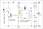
I have made this circuit to control an Airsoft gun I am building, see attachment
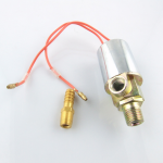
The circuit controls the opening and closing of the solenoid valve and how long it stays open and closed.
It will have 3 different fire modes, controlled by a select lever, still to be designed.
img034.jpg

Note the car battery is for testing and will be replace with lipo (11.1 or 18 volt).

I have some questions I am hopping to get sorted.
The circuit works as intended, but.

The AA's fire the solenoid ok, but, when connected to an air supply they will fire it only for a short time.
Disconnect the air the solenoid will fire
I assume the AAs just don't have enough power to drive the TIP142T is this correct?

I have thought of replacing the AA's with a 3.6 lipo telephone battery, would this last longer?
A combined power source is another option, but I don't know how to do this.

As noted in the attachment I had to change some parts, because of availability, could these be causing problems?

I did have the input jumper set to programe, would that drain the power?

If there is an easier way to do this project please let me know

Thanks for your time an comments

Derek
 

SAborn

Senior Member
Is the 12v negative connected to the AA negative, as it should be to form what is called a common ground.
 

Paix

Senior Member
Hello Derek, and welcome to the forum.

Unusually the Australian and NZ contingent seem to be otherwise engaged.
Dare I ask where about in NZ you are? We have a number of NZ regulars that will be interested as it will allow them to better direct you to local assistance or component suppliers etc.

You say that you have the valve operating, but apparently the AA batteries which are driving the 08M2(?) chip flag very quickly in operation.

Are you able to post the code that you have, in order to rule out anything dodgy that might be contributing to that? You have me out of my element. I normally consider a general purpose NPN transistor or a logic FET as my safe ground and probably have as much experience with a Darlington Pair arrangement as yourself.

The solenoid works just fine without the air pressure, but once the air pressure is applied, the triple AA battery life becomes minimal?
It's difficult to figure where the problem is without knowing something about the solenoid you are using.

Do you have a part number or data sheet for the solenoid valve or a URL where we can go to find data for it? The resistance and other ratings will be of great help in working out exactly how it is best fed. The 1k resistor at 5V would limit the current to 5mA, which isn't a big figure and seems a fairly typical value although I have seen circuits with that value going as low as 50 ohms, which would start to concern me.

According to the data sheet for the TIP142T the voltage needed to switch the Darlington Pair on is in the order of 3V, I'm wondering if the resistor needs to be slightly smaller, say 470 or even 330 ohms? If you have either of those values available to you you might like to try substituting, if someone with a better idea doesn't come along in the next hour or so?

The TIP120 seems the better bet of the three candidates mentioned on the diagram with a max turn on voltage of 2.5V. They all seem to have a gain of around 1000.

Here is the TIP102 data sheet for completeness,

What I do know for sure: the programming link only needs to be moved if you need to use pin C.5 (the serial input pin) as an input for your program. There are other things to consider, but it's not often that you are pressed to use it and it has no bearing on your circuit, rest assured.

The 1N5822 is a 3A Shottky diode, MASSIVE overkill, but it will do the job eminently. A bit like giving the kids gold coins for their pocket money . . . As you rightly pointed out a lesser rectifier diode would have done the job just as well.

The other question is how long are the pulses that you are sending to the solenoid. This is a question that your code would answer directly.

Not a good answer, I'm afraid, but something to be thinking about until the cavalry arrive.

I can imagine that the valve would require more energy to overcome the working air pressure. What is the air pressure in use?
 

LazyboyNZ

New Member
Hi

Thanks for the replies.
I live in a slightly broken christchurch

I had a play around after posting and now think it might be the code.

The first part of the code I can hear the solenoid clicking and when it gets to the loop it then will fire the solenoid.
I cange the batteries back to some old ones and got the same result.

So it could be the timing is too short.

I am off to work shortly and will check in around 1.30 am when I get home.
Heres the code

;2 1 1shots
high 4
pause 20
low 4
pause 500

high 4
pause 20
low 4
pause 1000
;2 shot burst
high 4
pause 20
low 4
pause 30
high 4
pause 20
low 4
pause 1000
;3 shot burst
high 4
pause 20
low 4
pause 30
high 4
pause 20
low 4
pause 1000
;Auto
main:
high 4
pause 20
low 4
pause 30
goto main.

Air Horn dtails

Brand New Chrome Air Solenoid
Max PSI: 180
Power Source: both for 12 volt & 24 volt DC
Material: Chrome plated all metal housing
Air Outlet: 1/4"NPT-MALE
Air Inlet: 1/8" NPT FEMALE
Includes a 1/4" BARB Fitting for 1/4" ID Hose.
Perfect For Air Ride Systems
Measured amps at 2.1 amps

Solenoid valve.png
 
Last edited:

Paix

Senior Member
Yes, the pauses are in milliseconds and I would imagine that the valve would take a finite time to operate, particularly under pressure, rather than when disconnected from an air supply.

I imagine that air preservation is high on your mind - self contained rather than having a hose follow you around. Visions of a sanger built of sandbags, a long hose compressor and an even longer electrical extension cable as you hose your mates with airsoft machine gun fire . . .

Not knowing how you arrived at your figure of 20mS for the on period, perhaps you might consider writing a loop that gives a five or six shot burst for tuning purposes, with the off time at 100ms, one group at the current 10mS gas on time, and with each group increase the gas timing by a few milliseconds.

I've been out all afternoon and am going out again in a few minutes - RAYNET Group, but will be back later and will write a bit of code for you to consider. The point being that increasing the on time and decreasing the off time to keep the firing rate the same over the group, you should probably be able to hear the difference over ten groups and come to the conclusion that there is a sweet spot in there somewhere. Having decided which is the most optimum gas on time in operating conditions, you can set that and start playing with the off time, to get the maximum rate that you want, without getting into less than optimum gas off time territory. Yep, one parameter at a time.

The fact that you turn on the output for 10mS doesn't necessarily follow that the valve is actually open for 10mS! Your description of "Air Horn valve" put me on the right track similar to this.

Back later. :)
 

hippy

Technical Support
Staff member
I did have the input jumper set to programe, would that drain the power?
On the 8-pin protoboard it's a link on the programming Serial Output pin; to route that output back to the computer ( for programming ) or to other hardware ( when running ). As you have your transistor on output 4 you can leave the jumper in the programming position.

That should not drain the power and nor would I have expected simply switching the transistor on to do that either. Check that there aren't any shorts on the board. If you have a multi-meter that can read DC current then connect that in series with the wire between the battery + and the board + to see what currents are being drawn.
 

westaust55

Moderator
Based on the transistor already in use, if driven into saturation to keep the collector to emittir voltage down.

V e(sat) = 2 volts
With a 2.1 amp load that is still 4.2 watts of beat the transistor must dissipate so a good heat sink may be order.

Gain in saturation is about 500.
So you need a base current of at least 4 mA and 5 mA is better.
vbe(sat) is 3.5 volts so voltage across resistor is only 4.5 v - 3.5 v = 1.0 volts.
500 ohms is thus the max base resistor value (1/0.005) so use a 470 Ohm base resistor.
 

LazyboyNZ

New Member
Thanks for the replies.
weataust55 I have changed the resister to a 470 Ohm and it does improve things.

hippy I cannot connect the milti-meter in series as the battery cables are soldered to the board.
How ever I did connect the multi-meter to the battery case and the solder point for the + wire on the board and got 1.6 VDC.

After reading this topic and some googling my thinking is

1. increase the board power to 5 volts (not sure how to do this)

2. change the TIP 142T to a TIP 120 or a logic level mosfet, or some other transister, what would be best?

3. work out how to power this from an 18 volt lipo battery, 12v for the solenoid and 5v for the Pic

What do you guys think
 

Paix

Senior Member
increase the board power to 5 volts (not sure how to do this)
work out how to power this from an 18 volt lipo battery, 12v for the solenoid and 5v for the Picaxe
How about your +12V, with heavy decoupling large uF capacitor and one of these carefully adjusted to deliver the +5V supply, which really isn't too demanding.

If you were to use 18V, presumably also to give the solenoid a bigger kick (assuming it's rated 12V/24V but I think you said it was). The regulator would deliver you 5V from that as easily as it would from 12V.

change the TIP 142T to a TIP 120 or a logic level mosfet, or some other transistor, what would be best?
Buy in a couple of TiP120 and a logic level MOSFET to rattle around your bits box, as contingency for this project or earmarked for another one. Always handy to have (bigger bits box that is)!
Give the TIP142T a chance with the beefier supply.

You could use 6V worth of batteries for the Picaxe and stick a diode or two in series to drop the voltage to below 5.25V, but measure it – Shottky diodes 2N5xxx have a low forward voltage drop and you seem to have some in your bits box I noticed . . .

Bit of code promised follows later today. Must have a sleep first.
 
Last edited:

hippy

Technical Support
Staff member
hippy I cannot connect the milti-meter in series as the battery cables are soldered to the board.
You could temporarily unsolder the wire and replace it with a flying lead, or cut the wire then solder it back together when done.

The PICAXE, even when triggering the transistor, should not be draining the batteries rapidly ( unless you had poor quality or low-rated batteries ) and increasing the PICAXE supply voltage would probably not resolve that issue.

There seems to be some sort of fault with the circuit or wiring which it is best to identify and resolve before considering other power supply solutions. If there is a short or fault then using high capacity batteries could cause damage to your PICAXE, circuit or battery.
 

LazyboyNZ

New Member
hippy, I unsoldered the postive led between the battery box and board, connected the multi metre and got 4.02 volts.
I checked the batteries and they were all over 1.6v's, so I don't think the problem is batteries.

In testing, I have found that changing air pressure, changes the time needed to fire the solenoid for the first time after that it works fine.

If I program the Pic to loop, or repeatedly switch it on and off, (on single shot mode), it will take a little time to fire the first time and then fires happily until powered off.
It seems to me it needs time to charge up and does not discharge completely between pulses.
It could be the solenoid sticking, its a cheap solenoid.
 

Paix

Senior Member
Here is some code, written but 'not yet checked'. Potential grey area is in the trigger checking, so hanging a LED on the end of the 1K resistor on pin C.4 to initially view what is happening and checking for correct operation, before connecting up the transistor and 12V circuit items.

It may give you an idea of what you may wish to think about for your initial project and further if you choose to develop a MKII device.

Get yourself a few small inexpensive breadboards and link wires and hack as much together on that, before committing to soldering parts together. it will save you a lot of time in the long run.

The essentials are a trigger switch and two switches to control the firing pattern, single shot, double shot, triple shot and automatic. Decoupling is shown on the circuit, but there is no download circuity. I use an AXE029 download adaptor which I plug into all my bread boards as necessary for programming development, any necessary communication and debugging. I use three fly leads to connect it to any chip.

AirMultiTap.png
Code:
#picaxe 08M2
setfreq m4 ' 4MHz default. If this is changed, then the value
           ' of timing requires to be scaled accordingly.
           ' Paix 12 Jan 2014 for 
' Title AirMultiTap 

' The weapon safety is the power switch!
' Facilities: Trigger and compound shot-pattern selector.

' A bigger chip with more pins would perhaps allow for
' inclusion of the following additional or modifiedfacilities:
'               a weapon test mode
'               reload switch sensing (mag off, mag on)
'               software safety switch
'               shot indicator
'               sound output 

'Pin/port.pin symbols
symbol shotopt0 		= pinC.1 ' two-pin pattern selector :  error, was pin.C1
symbol shotopt1 		= pinC.2 ' 00 one shot, 01 double tap, error, was pin,C1
                    		     ' 10 triple tap, 11 automatic.
symbol trigger  		= pinC.3 ' choose shot-pattern and execute, error, was pin.C4
symbol bang     		= C.4    ' output pin

'Variable symbols
symbol poplength    = b2 ' trigger pulse length to activate the solenoid
symbol popspace     = b3 ' time between automatic rounds

symbol lockout      = b4 ' debounce, on confidence level
symbol spare        = b5
symbol shotselector = b6 ' used by shooting pattern select 
symbol burstcount   = b7 ' multiple shot iteration counter

poplength = 80					 ' gas on time - These are the values to alter
popspace  = 1000				 ' gass off time - to tune the shot rate

pause 1000
MAIN: ' this is the weapon loop
if trigger = 1 then ' untriggered
  lockout = 0
  pause 10					' spare pause!
  goto MAIN
endif

if trigger = 0 and lockout = 0 then
  gosub SHOOT
  lockout = 1
endif
goto MAIN


SHOOT:
  ' read the shot pattern selector switches.
  ' the switches are static, so no contact debouncing is required.
  shotselector = shotopt0 * 2 + shotopt1 ' returning 0, 1, 2 or 3
  sertxd ("TT", #b6, cr, lf)
  select case shotselector
    case 0
      gosub TAP
    case 1
      gosub DOUBLETAP
    case 2
      gosub TRIPLETAP
    case 3
      gosub AUTOMATIC
  endselect
  return
	
TAP:								' This subroutine is used for all gas on/off operations
  high bang					' gas start
  pause poplength		' gas on period
  low bang					' gas stop
  pause popspace		' gas off period
  return
  
PiP:										' This is for sound instead of gas. POP rather than TAP
  setfreq m32								' I have not listened to the tone value though - watched a LED! Ian
	sound bang,(80,poplength)
	sound bang,(0, popspace)
	setfreq m4
	return

DOUBLETAP:
  for burstcount= 1 to 2
    gosub TAP
  next
  return

TRIPLETAP:
  for burstcount = 1 to 3
    gosub TAP
  next
  return

AUTOMATIC:
  do
    gosub TAP
  loop while  trigger = 0                      		
  return
This code was re-written and inserted circa 23.59 Sunday 12 January 2014 - Checked and good to go.
X X X X X X X X X X X X X X X X X X X X X X X X X X X X X X X X X X X X X X X X X X X X X

Any problems give me a shout and I'll fix it. I will also write that subroutine so that you can test a range of valve opening times and repetition rates etc.
 
Last edited:

Paix

Senior Member
@LazyBoyNZ, I have just seen your post #12. I wonder if the apparent stiction is caused by an excessive initial pressure build-up and if it might be ameliorated by using a slightly longer pulse for either a single shot mode or as the first pulse in a train of pulses.

Have you been able to check out the effects of varying the pulse width at all yet?

= = =
No rush, I will check the code over the next couple of days, I normally read all the posts, so I'm sure that I'll catch anything. Just have a few other things to be doing too.
 
Last edited:

LazyboyNZ

New Member
@ Paix " excessive initial pressure build-up" I think that could explain it

I have been playing with single shot pulse lengths, at about 95 psi, I need somewhere between 50 and 100 ms first shot, but if I program it to say 20 ms on, 30 ms off, after powering it on and off a few times it fires very well.

Maybe some kind of extra power boost for the first shot is needed, a capacitor maybe.
 

Paix

Senior Member
@LazyboyNz, here are a few questions to get a better feel for the behaviour. I'll try to be as clear as I can and hopefully I can note your responses and tailor the program behaviour to accommodate both yourself and the requirements of the solenoid.

You will have to check the behaviour over what you consider to be the realistic operational pressure range. AK47s have finite limits to the number of rounds that a magazine will hold, so you don't want to be shooting until it wimps out, gasping a last breath . . . I imagine you want a guaranteed operation range for the pressure. You will understand that I have a keen sense of irony, cynicism and humour. It all leaks out from time to time. :)

Realistically, what is the maximum rate of fire that you seek? Ammunition and gas being a finite resource in a self contained device and you are possibly emulating the fire rate of a real world weapon. Whilst a MAC10 has an astounding rate of fire, it wouldn't make much sense to put a dozen slugs in the same brain on the battlefield.

Assuming that it's a static over pressure condition, if you were making slow single shots, how long between shots before the problem is there for each shot?

It may not be of any help, unless the voltage is sagging briefly, but you could try a large electrolytic across the +12V supply close to the solenoid / transistor. On a similar note, how hefty is wiring of the +12V circuit? Skinny wiring there might be introducing current losses. Unlikely but worth mentioning. Look at the hefty wiring that they use on those quadro-copters drones for running the motors. The +12V on the Low Tension side of an old vehicle ignition coil was fairly hefty too, for the same sort of reason.

For testing, you can comment out the MAIN section of the code with block #rem #endrem statements and put in your own gosub instruction, to drive any one of the subroutines. Any changes that I make or you ask for, I'll try to make them as complete subroutine replacements so that you can effectively comment out the old and plug in a new software component in your editor.

Best get to bed here, as it's 6.20AM already.

What did you think about the shot selection "one, two, three and auto"? I obviously don't know anything about AirSoft gaming and the rules and conventions that participants try to follow. To that end, Is a finite magazine size something that might be of interest once you have your basic model tuned and working consistently?
= = =
[aside] I should use simple optical character recognition to detect the difference between bees and wasps flying up a window. Seen from underneath, bands are wasps and chevrons are bees. I think that a Raspberry Pi should be able to do the OCR and a laser to take out the wasps . . . or a high pressure blast of air . . . and you thought that I was just helping you :) Impractical, but a bit of technical fun perhaps. [/aside]
 

LazyboyNZ

New Member
Quick reply off to work

Your program and schematic are just what I am looking for, its great;).
Some of the wiring is on the skinny side so I will look at that tomorrow
Thanks very much for your help
 

Paix

Senior Member
On the skinny wiring side, the areas that will need care are on the 12V side of things and a substantial ground rail/track.

It's always good to have generous grounding, but here because because of the disparity of the currents in the two halves of the circuit, we need to ensure that it's all up to the higher current standard, all the way back to each battery terminal, as far as is practical.

Often with solenoids the first indications of problems are that the MCU glitches or resets in sympathy with the solenoid operation. We don't appear to be anywhere near this sort of territory, so fingers crossed.

I hope to be in a position to at least put the code through the simulator and driving an LED in around six hours time after I have finished up elsewhere. I'll clear any code issues and check out a flexible test routine that might be of help.

The one thing that is cardinal at the moment, is the time it takes for the stiction problem to re-manifest itself if you were using single shot mode exceedingly slowly. It being a case of characterising the problem that you already have a feeling for. We're just after the devil in the detail now - hopefully.

The inconsistency that we see are things that I have heard about in one way or another for a lot of my life, although I have have not been in a mechanical design area. It has to be something that is working close to the one or other edge of it's envelope, which here might any one or more of pressure, voltage, current or time.
 

LazyboyNZ

New Member
I have cracked the delay problem, I connected up 2 car batteries in parallel and can now fire the solenoid at 95 to 100 psi on a 4 ms on, delay.
So for the target pressure range of 90 to 150 psi, I will need a stronger battery or different solenoid.
My thought are to get something like an 18 volt battery.

By the way the 3 AA batteries are working fine so don't think there was a problem there.

When running on 12 volts the maximum pressure is about 95 psi, the delay when firing single shots reappeared at about 5 seconds.
The on delay needs to be around 50.ms.

I also replaced the skinny wiring


Some specs for this project are
pressure range 90 150 psi
Air conservation is important, so short on time is needed.
Rate of fire, 120 to 240 round a minute
Picaxe batteries to be housed in the gun, solenoid battery in the gun or in a pouch or back pack along with paintball air tank.

Paix is this enough information.

Thanks very much for your help and on going support
 

Paix

Senior Member
I t is excellent that you have cracked the delay problem. Who would have thought that a car battery might have sagged that far or the instantaneous current demand that great to require two in PARALELL (12V double the current capacity)?

I note that you are considering an 18V battery . . . do you spot the contradiction here? Was the problem a lack of current or lack of voltage? And I wonder how much the skinny wiring may have contributed? Reading further a combination of both low voltage and current starvation seems to be the answer. So an 18V battery seems like a good choice to give you guaranteed operation over the specified air pressure envelope.

I had suspected that valve stiction was reminiscent of a device operating at the lower edge of it's envelope, but it's excellent that you have nailed the problem. and I'm much the wiser for it. I Googled for pneumatic valve stiction and was overwhelmed by the amount and technical content of the of material returned. Not really pertinent, but definitely a subject or concern in the process industry.

You will smile! I was trying to get you to hold down your firing rate and you come back with figures which I thought to be exceedingly conservative, so I did a bit of Google research and my findings support your thinking, but in the short burst arena, my thinking varies – fire for effect!

From the original solenoid spec , 12V at 2.1A is 5.7 ohms or 25.2W, it would seem that a 7.2Ah battery should be capable of supplying the necessary motive force, in the short term and put the car battery into perspective, so I can well see where need for 18V comes into play.

I'm not really a gun person, having only ever fired Lee Enfield .202”, .303”, 7.62mm SLR,.62 Bren and one shot with a friend's shotgun at a gate post, which didn't impress me at all. I think that the lead shot did more damage to the environment than to the gatepost that it was aimed at, and hit just in case there might be any doubt in the matter :)

GPMG
750rpm = 12.5rps cyclic
200rpm = 3.3rps sustained * period per shot = 300mS (auto)
100rpm = 1.6rps
100 round belt

HMG
600rpm = 10rps cyclic * period per shot = 100mS (tripletap)
50 round belt

LMG
1000rpm = 16.6rps cyclic
100 round belt

LSW
750rpm = 12.5rps cyclic
30 round magazine

Steyr Tactical Machine Pistol
900rpm = 15rps cyclic * period per shot = 67mS (doubletap)
50 round magazine (?)

H&H MP7 PDW
950rpm 15.5rps
20, 30 or 40 round magazine

This makes me suggest the following candidates, as may be ascertained from the above.
Single shot, as fast as you can cleanly pull the trigger.
Double tap 15 rounds per second (900rpm) = 67mS
Triple tap 10 rounds per second (600rpm) = 100mS
Automatic 3.3 rounds per second (200rpm) = 300mS

You don't need a particularly fast sustained automatic rate of fire, because your range is significantly less that 1800m so the spread in a modest sweep is not too much!

This is all taken from what's out there in the real world in some way, shape or form and my own feelings on the matter with economy of ammo and air also being high in my mind. Can you tell that I am not thinking about hunting for food?

So, this is the proposed spec that I suggest, but it is more for you to think about and then correct me if you think that it isn't what you feel is the best for you! Sometimes I think that rounds per second give a better feel for the shooting rate, although the standard appears to be to express the figure as rounds per minute!

. . . Continued.
 

Paix

Senior Member
. . . continued.

I have cracked the delay problem, I connected up 2 car batteries in parallel and can now fire the solenoid at 95 to 100 psi on a 4 ms on, delay.
So for the target pressure range of 90 to 150 psi, I will need a stronger battery or different solenoid.
My thought are to get something like an 18 volt battery.
10mS trigger pulse period
Overall duration per shot, rate per sec/min
Double tap 67mS, 15/900
Triple tap 100mS, 10/600
Automatic 300mS, 3.3/200

When running on 12 volts the maximum pressure is about 95 psi, the delay when firing single shots reappeared at about 5 seconds.
The on delay needs to be around 50.ms.
This appears to be for a worst case and makes me think of the gas regulator on the SLR, normally set in the middle of the range, but when in combat with a hot rifle then if it starts failing to automatically cock the weapon properly, then the answer was to max out the regulator and accept the extra recoil a a minor inconvenience when the alternative was to present a more opportune target.

Along with a magazine switch and counter, a virtual gas regulator adjustment switch might be an enhancement for a MKII to get you out of a potential low battery during extended AirSoft combat.
(as long as your gas hasn't run low)!

I apologise for for any repetition, but it's pretty much a slow speed brain dump. I have some reading to do and hope to get a look at the code in the PE later this evening and should have something checked, re-timed and ready for your tomorrow.

Hopefully then we will be in a full feedback loop. Once you are happy, I'm hoping that you will take all the thinking and figures, specs etc. and perhaps put it together in a separate thread as your completed project, containing all the information to allow someone else to take the same route without having to cut and try when it comes to component sourcing, timings, pressures voltages etc. and your thinking behind your design decisions.

Back later.
 

rossko57

Senior Member
Some thoughts from the world of gaseous fuel injectors - which after all are just fast-acting solenoids. They are much smaller than your valve, hence faster acting - less mass to accelerate. A 4mS pulse is practical for them ... but this is at the low extreme of the operating range. I would have thought your chunky valve would be considerably slower to act than that, indeed I suspect the 50mS is more like its true full-stroke operating time.
<img>http://v8dualfuel.com/components/images/front_romano_fast_inj.jpg</img>

It is possible to use a scope to observe solenoid current to determine opening times - you can usually see a step when its done. But that still doesn't solve how to determine closing times - which will also affect the overall gas delivery shot. No makers data for your chosen valve?

For any valve, you have to apply a minimum pulse to get it moving. You need to apply a longer pulse to get it to open fully. My suggestion is that your short pulses may not be opening your valve fully.
You might still be getting enough opening for your action, but it might not remain consistent with different apparently identical valves or at different states of battery charge (this kind of thing is important for fuel injectors). I feel it is possible you may be tuning for a marginal condition, and start getting inconsistencies if the climate, pressure, or battery varies.

A crucial factor in fuel injectors is rebound control; there we're aiming for consistent opening at high repetition. It really is amazing how much difference something as simple as an aged bump-stop rubber makes here.
My suggestion here is that the apparent 'stiction' effect you observe is the 'normal' inertia of the solenoid. You're not seeing it when youi fire in bursts because the valve innards are still rattling around before the next pulse comes.

Anyroad, that's just theoretical stuff. Two suggestions ;

Look for a smaller (hence lighter hence faster acting) solenoid for more accurate and repeatable control of gas shots. You might even find an old LPG autogas injector will do. You could try, but I suspect petrol injectors will flow too small a volume for this.

Consider a capacitor discharge circuit for your solenoid driver, even just a capacitor on the supply will simulate your "two parallel battery" test without the extra lead weight.
 

Paix

Senior Member
Many thanks for your technical input Rossko57. I know very little about the subject, but what you say rings true and makes good sense.

The large capacitor is a good idea, as is the 'LPG autogas injector'. From a practical standpoint we are tied to what we presently have, presumably driven by price and availability. You have expanded my understanding of potentially suitable air/gas devices - definitely not my field.

Perhaps a rethink on the faster repetitions may be in order and I'm sure that Derek will take on board what you have said.

It's good that forum members come from different disciplines and areas of expertise, as it certainly helps break down the otherwise inter-disiplinary tunnel vision that might otherwise exist and slow the spread of knowledge outside the purely Pixaxe arena.

Appreciated.
 

LazyboyNZ

New Member
Paix
The proposed spec are good and I would go with them.
The 18 volt battery is a bit hit and miss, hopefully it will have enough power to operate at the desired level.
Airsoft guns use Lipo or NiMh battery packs in the range of 7.2 to 9.6 volts.
They are light and I thought having 2 in parallel would give me the grunt needed.

I will write it up as a project once completed.

Rossko57,
I think you are right on the money in regards to the operating envelope of this valve.
The valve is a cheap, Ebay, copy, so I suspect quality too vary from one to the next.
I like this valve because its shape and layout, fits nicely into the gun and another couple I have in mind to make.
The amount of air required is quite small, about 10 cm3 per shot
Consistence shots (within + / - 2 or 3 fps) is needed.

I looked at the injector valves and think the flow may not be enough, a truck one might do, although it would need 24 volts.
What sort of flow do you get from them?

The LPG injector is something I will follow up on
The capacitor discharge circuit interest me as that would reduce the battery size and costs, what is needed for this?
 

rossko57

Senior Member
Autogas (LPG for cars) gas injector specs are hard to find, but these are absolutely typical
http://www.europegas.pl/documents/Magic_Jet_tech_spec.pdf
50cm3 per minute may be too far small for you. You could double up injectors perhaps.
Note opening + closing times in the 3.5mS league. Blistering fast but probably not much use for you because of low flow. Does illustrate though the smaller the valve you can get away with, the better for speed. The faster they are, the smaller the open/close time is as a proportion of the overall operation, and the more closely you can control the size of the delivered dollop.

A trick is peak-and-hold drive. The coil driver delivers a big whack to get the valve opening fast, but reduces current after a few mS to a lower level, sufficient to hold the valve open. When switched off, the smaller current decays more quickly and the valve closes faster. Saves a bit of energy/heat too.
At its simplest it can be done by driving a coil at 12V for a couple of mS, then reducing drive to 6v or even 3v to reduce the current. 1:4 current ratios are generally enough to hold open a valve.

That could in principle be done with a variation on capacitor discharge driver. Feed a large capacitor from the battery by a low-value resistor. Use that capacitor as the power supply for the coil and its driver transistor. When you activate the transistor, the coil will initially get a current rush from the capacitor, which will drop off as it discharges towards a steady level controlled by the low-value resistor. When the driver is off, the capacitor will recharge via the resistor.
It'll probably work best with something like a 12V supply over-driving a 6V rated coil. I'll bet your stiction goes away ;) Sounds alarming but it is a standard practice for peak+hold drivers, so long as the peak part is of gauranteed limited duration. But no skinny wires in this circuit!
Your proposed 18V LiPo driving a 12V coil may well be just the job if you minimise losses in the driver.
There are certainly more sophisticated ways to do this, look up fuel injector drivers, but this is simple.
 

Paix

Senior Member
Instantly looks for an engineered solution = LM1949. Use it to drive coil from +18V (or more) via a beefy logic level FET

Availability - not a recommendation but means not paying DigiKey or Mouser prices and horrendous knock ons, like postage and duty.

Another thought, for later, +12V fed to solenoid via rectifier diode. Capacitor and free-wheel diode across solenoid to FET drain. +24V from small voltage doubler also feeding the capacitor via a current limiting resistor. Diagram shortly.

= = =
Currently I have an 08M2 driving a logic FET to key an old fashioned ignition coil with a nice short pulse every couple of seconds. It doesn't require smart drivers, it works at the mental level. Electric fence to keep horses away from the drones and my workers . . . :)
 

LazyboyNZ

New Member
Rossko57 I rang a local LPG converter, unfortunately, he said the max pressure was 60 psi, which is too low for my project :(

I have read about the peak and hold system for the solenoid, Paix electric fence sounds like a nice simple solution.
I prefer simple and reliable to sophisticated, brains too old for that.

My brother in law has some 18 volt battery powered tools,I will borrow a battery and do more testing

Heres what the project looks like

picture of the gun
http://i215.photobucket.com/albums/cc102/Lazyboynz/DSCF0460.jpg

An earlier pnuematic attempt at making the internals
http://i215.photobucket.com/albums/cc102/Lazyboynz/DSCF0459.jpg

And a video
[video]http://s215.photobucket.com/user/Lazyboynz/media/DSCF0461.mp4.html[/video]

This version wasted to much gas, the sssss sound after each shot.

Just a note
This stuff is all new to me, I still don't understand how electricity at the plug the moment I turn it on.
I even learned to solder last week, but that's what its all about isn't it
 

Paix

Senior Member
PulsePlus.png

@Roskko57. Other than the fact that I seem to have a couple of wobbly diodes, I hope the idea seems clear.
This hopefully represents the solenoid keyed by a pulse to gate of the MOSFET as normal.
Concurrently a pwm pin is chopping at a several kHz the output of a GP NPN transistor, with the chopped output going into a voltage doubler (two diodes and our boost Capacitor) there should be a low value current limiting resistor immediately to the right of the cathode of the right hand green diode.

The brown diode is for isolation and I think that the left hand fly back diode probably compromises everything.

Ah well, the problems of thinking out loud . . . that's something that I might play around with at a later date, but not now.

@LazyBoyNZ. My, you certainly seem to have modelling talents that I don't have. Hopefully if you learned to solder last week, you managed to get hold of some decent 60/40 tin/lead solder and not this lead free muck that newbies get foisted off with. It may cut the mustard on the production line, but it sure doesn't lend itself to happy hand soldering.

Really Interesting video. I somehow had visions of the well defined whacking sound that I am familiar from a compressed air stapler . . . Not recommending staple overflights of course. Ah well, at least the Sten didn't have the reputation of the Stirling for catching wayward pinkies in the cartridge eject port.

Need to get to bed, not moved the code yet to check it out on the PE and put it to a Picaxe and breadboard. . . .

Are skies really that blue . . . it seems to have been a while . . .

Code in my tomorrow Wednesday This idea is left for historical reasons, but as SABorn has pointed out is frankly just embarrassing. Smile at it, but don't try to do anything useful with it - it's BAD
 
Last edited:

AllyCat

Senior Member
Hi,

The brown diode is for isolation and I think that the left hand fly back diode probably compromises everything.

Ah well, the problems of thinking out loud . . . that's something that I might play around with at a later date, but not now.
Yes, IMHO the circuit as shown won't/can't work because, for example, the left hand diode resricts the positive voltage excusion and the negative of the electrolytic doesn't go anywhere useful. But the concept of a raised "++" supply rail to "kick" the solenoid is probably the way to go.

Here are two possibilities, the former perhaps better for low duty cycles (e.g. the solenoid operated for less than 10% of the functional time) and the latter for high repetetion rates:

The first is a simple "bootstrap" circuit (sorry I've no schematic design package to hand). + of the (>24 volt rated) "bootstrap" electrolytic capacitor goes to the solenoid and receives current from the cathode of a diode (with anode to the normal + rail, say 12v). Negative of the electrolytic goes to ground via a (lowish value) resistor, so that it initailly charges to + volts. A second "power" Transistor, typically a PNP, (or possibly FET) sits between the + rail and the negative of the electrolytic, such that it pulls the negative of the electrolytic up to + volts (thus the positive terminal goes to ++ volts) at the same time as the "normal" FET is fired. Note that this "bootstrap" transistor may itself need a driver stage because it must be able to continue to conduct when its base (or gate) is pulled near the + rail.

When the solenoid is fired, the voltage from the electroltic falls from ++ (say 24v) down to + (say 12v) at which point the supply diode comes into conduction and maintans the current flow to the solenoid (with a forward diode drop of reverse voltage across the electrocolytic which is probably safe).

The alternative method (which Paix was probably attempting) is to use a (lower-power) voltage upconverter to generate the ++ voltage. Negative of the electrolytic goes to ground with the positive receiving current from cathodes of two diodes, from the + rail and from the boost choke/transistor. However, you probably need to run the PWM with feedback control (to reduce PWM when the required ++ voltage is achieved). The issue with a "flyback" converter is that (a fixed amount of) enegy is stored in the choke and then "released" to the capacitor, which can potentially continue to very high voltages (and probable destruction of capacitor or semiconductors). So the PWM needs to be "wound back" to (almost) zero duty-cycle once the required ++ voltage is reached.

Cheers, Alan.
 

LazyboyNZ

New Member
I borrowed an 18 volt battery and found that it would open the valve at about 110 psi.
with 150 psi the valve wont fire even with 24 volts.

I will need the volts multiplier or a different solenoid,

I will setup my paintball remote air system and see if I can borrow a chronograph to see what fps (feet per second) the gun is shooting at (needs to be around 350 fps).
That will tell me the pressure I need .

Looking at different solenoids, some of them have a current rating of 200 mA's. Does this mean they would be more efficient?

Thanks again for the help and education
 

rossko57

Senior Member
You quoted a spec for the valve that doesn't work "Max 180psi". Now, whether that means max safe pressure - the burst pressure if you like - or max working pressure - the pressure it can still open at - is not clear. These are two different specs you ought to take into account when shopping around.

As you increase pressure, you will need longer pulses. Losses in the driver will become more significant. Were you testing at high pressure just across the battery, or using your driver in on/off mode, or with pulses?

You don't get something for nothing; a coil at 200mA can't do as much work as one at a couple of amps. That might be because the the mechanism is lighter (hurrah, faster?) or smaller (boo, low flow) or many more windings (boo, slow). You either need to look at more of the specs or just try it.

You could solve a lot of problems by finding 6V rated coil, but they are rare?
 

LazyboyNZ

New Member
@ rossko
yes a 6 volt are rare and valves are very expensive here.

I tested using the driver, single pulses ,but did not extend the pulse very much, will do more later today.
Did not try the valve straight off the battery

I jumped in and ordered a couple of valves

Description Specifications
Voltage 12 DC Volts
Current 400 mA
Default Mode Normally Closed (valve closed when coil is not energized)
Valve Type Direct Acting
Inlet/Outlet 1/4"
Max Pressure Air: 140 PSI Water: 80 PSI Other Liquids: 60 PSI
Suitable Applications Air, Water, Oils, Vacuum
CV Rating 0.22
Max Temp 170F
Valve Response Very Fast
Duty Rating 100% (rated for continuous use)
Materials
Valve Body Aluminum
Plunger Tip NBR

and this

Product Name Solenoid Valve
Model No. 2V025
Fluid
40 Micron Filtered Air
Operation Type
Direct Drive
Type 2 Way 2 Position Single Head Type
Power Consumption DC 12V 250mA 3W
Working Pressure 0-10kgf/cm2
Temperature 60C
Joint Bore Size(Approx) Inlet=Outlet=G1/4"
Threaded Port Size(Approx) Air Inlet=Air Outlet=13mm
Hex Connector Inner Dia(Approx) 15.5mm/ 0.61"
Mount Thread Diameter 3.5mm/ 0.14"
Overall Size(Approx) 7.7 x 2.2 x 6cm/ 3" x 0.87" x 2.4" (L*W*H)
Color Silver Tone, Black
Indicator Color Green
External Materila Plastic, Alloy
Net Weight 139g

They should arrive later this month
 

SAborn

Senior Member
I notice the use of a flyback diode across the solenoid coil, i would have done this too, but from a post some years back someone done with trying to build a water droplet printer, it was recommended not to have the flyback diode as it slows the closing time of the coil/valve.

Also i can not see how the cap in Paix circuit can work with the inductor and coil, as its isolated to ground when the fet is off, i would have thought you would be charging the cap via the inductor when the coil is off and dumping it to the coil when the fet switched on.
 

rossko57

Senior Member
it was recommended not to have the flyback diode as it slows the closing time of the coil/valve.
This is true ; can also be called a flywheel diode, which is pretty descriptive of what it does to coil current.
(Goes without saying it's there for a reason though, and anyone omitting it needs to cater for what has essentially beome a spark generator.)
Peak-n-hold drive helps by reducing the current before the 'off' event, but it'll always take some finite time to close.
 

Paix

Senior Member
update - @SABorn, :) I have put a warning on the drawing at post #39 in case some optimistic newbie happens across it and thinks that they may have hit paydirt . . . Wrong end of the rainbow - again!

@LazyBoyNZ, post #13(?) code replaced with rewrite that I have also checked with 08M2 and LED (no actuator). It's now good to go and the rates, where applicable, are around that of a Sten gun. Sorry that it has taken me longer than I anticipated, but that's life getting in the way.
= = =
With PiP replacing TAP in the code it might be the basis of a childs toy, replacing the FET with something less able.
 

LazyboyNZ

New Member
Paix thanks for the code replacement. I am going to make up the circuit to test the code
In my post #31, I said 24 volts would not fire the valve at 150 psi, I tested again and found it works fine, must of had a bad connection to the batteries.
In doing so I managed to let out my first bit of magic smoke, hooked 18 volt up the wrong way round:( so need to replace some bits, .
I have read a bit more about volt doublers. Am I right in thinking the amps do not increase much, would this mean doubling the voltage would not give me enough current?
I have now filled my paintball tank and once I get a couple of fittings should be able to test things better with a longer lasting high pressure source.
 

Paix

Senior Member
Normally with a voltage doubler the amount of current is not part of the issue and it would naturally be significantly less. The doubling would be approximate and the current significantly less than half of the lower voltage supply.

My thoughts on the matter were significantly flawed. It seems that there is a lot written about driving magneto pneumatic actuators and most of it is written in formulaic terms that I can hardly draw, never mind understand . . .

Roskko57 and SABorn are significantly more adept at dabbling with pneumatic equipments and so may be a continuing source of assistance to further enhance the actuator driver.

I suggest the original circuit which should give the anticipated performance improvement over your earlier, mechanical, design which leaked air. From there it is probably sensible to seek a further enhancement using a pulse plus actuator driver. The changes would be relatively minimal in the great scheme of things.

I would have to excuse myself as anything other than an interested spectator, but perhaps one of Roskko57, SABorn, AllyCat or AAnother has circuitry that they can recommend? Any takers please gents? I'm more than happy to learn more about the subject.

It seems to have been the week in which at least three people have actively released magic smoke from their creations one way or another. Hopefully an area of quickly diminishing endeavour . . .
 

rossko57

Senior Member
I cannot claim to have dabbled much at all! but observe what works in a similar commercial requirement.

If it were me, I'd be looking for a power source double the continuous voltage rating of the valve. A 6v coil & 12v battery looks convenient, but finding a 6v coil looks like a stumbler.
A dual rated 24v/12v coil is really going to be a 24v coil that just manages opening at 12v. You might well get better results from 'real' 12v coils in your existing setup. Might be good enough, just experiment to find the pulse length needed at max pressure

Next step is 18v battery. Firing relatively short pulses through the coil, I doubt you'd need any further action.
If your required pulses to get air shots are very much longer than the minimum pulse you determined to open the valve at 18v, you might need to reduce energy consumption/heat by peak-n-hold.
If your required pulses are getting close to the valves minimum operating time, you might need peak-n-hold to speed things up.

The voltage doubler is only really viable if there's a fair amount of time between pulses to charge up a capacitor; that way the doubler current needn't be as much as the coil.
 

LazyboyNZ

New Member
rossko57, I did some research on batteries today and found there is no viable 24 volt solution, so this valve is not practical.
I have 2 12 volt ones on their way and have asked an inquiry into a 6 volt option I found on the web.

In the mean time I will play around with the code and valve I have, will keep you's posted.
 
Top