I've seen a couple of questions about software PWM on this forum. I'd never heard of using binary code modulation to do PWM before so when I clicked through to this link http://www.batsocks.co.uk/readme/art_bcm_1.htm. I thought I'd post it here where others will be able to find it. I also tried it out to see how well it worked for me.
I won't go into a lot of detail, you click through to the link to get that, I'll just sketch it out.
If the PWM value is 0x01010101 (decimal 85) then the common method we see for PWM is to put the output high for 65 units of time and then low for 170 units of time. The problem doing this on a PICAXE is that you have to do something 255 times every time through the PWM cycle in order to be able to adjust the PWM output for every possible value of 1 to 255.
With binary code modulation you only need to make 8 changes to the output in the same PWM cycle.
- Output the value of bit 1 and wait for 1 unit of time
- Output the value of bit 2 and wait for 2 units of time
- Output the value of bit 3 and wait for 4 units of time
- Output the value of bit 4 and wait for 8 units of time
- Output the value of bit 5 and wait for 16 units of time
- Output the value of bit 6 and wait for 32 units of time
- Output the value of bit 7 and wait for 64 units of time
- Output the value of bit 8 and wait for 128 units of time
So for my example PWM value of 0x01010101 the output is high for 1, low for 2, high for 4, low for 8, high for 16, low for 32, high for 64 and low for 128.
- High for 1+4+16+64 = 85
- Low for 2+8+32+128 = 170
You can also setup the values for multiple PWM pins ahead of time in variables. This enables you to do multiple channels of PWM at the same time just by writing the right variable to the ouput port at these eight times.
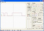
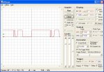
The first thing I did was get an idea whether it was going to be possible to get a reasonable PWM frequency. On an 08M at 8MHz this code gave a pulse train that was high for 0.2ms and low for 0.32ms (i.e. the 0.32ms is the time for the outpins + the time for the goto).
setfreq m8
dirs = %00000010
b0 = %00000000
b1 = %00000001
main: outpins = b0
outpins = b1
goto main
So if I set the value of bit1 and then change it to the value of bit2 the bit1 output has been set for 0.2ms. The PWM period will be 255 x 0.2ms = 51ms which is a freq of 19.6 Hz. 20 Hz seems too low.
- I could use a faster PICAXE. The same calculation for the 08M2 at 32 MHz would come in at 78.4 Hz but I don't have an 08M2 yet.
- The other alternative is to use less bits. If I only ouput the high 6 bits of the PWM value, instead of the full 8 bits, then it works out at the same 78.4 Hz on an 08M at 8 Mhz.
This was good enough to give it a go and it works!
Attached is the complete code for a simple RGB fader that runs on an 08M.
View attachment RGB LED Fader.bas
- The 78.4 Hz PWM freq seems fine, I couldn't seen any variation in the LED when using the same code to continually display a fixed set of 3 RGB values.
- The fading is not too bad with just 6 bits and on any PICAXE that runs at 32 MHz you'd be able to do 8 bits.
- I am still getting a bit of intermittent flickering, so it's not perfect, but I was pretty happy with the result. If anyone can spot the bug pls let me know.
- The delays probably need to be close to the right values to get smooth colour changes. I tuned the delay for each bit time using an oscilliscope.
- I tried using the pause command but it isn't accurate enough at very low values.
I won't go into a lot of detail, you click through to the link to get that, I'll just sketch it out.
If the PWM value is 0x01010101 (decimal 85) then the common method we see for PWM is to put the output high for 65 units of time and then low for 170 units of time. The problem doing this on a PICAXE is that you have to do something 255 times every time through the PWM cycle in order to be able to adjust the PWM output for every possible value of 1 to 255.
With binary code modulation you only need to make 8 changes to the output in the same PWM cycle.
- Output the value of bit 1 and wait for 1 unit of time
- Output the value of bit 2 and wait for 2 units of time
- Output the value of bit 3 and wait for 4 units of time
- Output the value of bit 4 and wait for 8 units of time
- Output the value of bit 5 and wait for 16 units of time
- Output the value of bit 6 and wait for 32 units of time
- Output the value of bit 7 and wait for 64 units of time
- Output the value of bit 8 and wait for 128 units of time
So for my example PWM value of 0x01010101 the output is high for 1, low for 2, high for 4, low for 8, high for 16, low for 32, high for 64 and low for 128.
- High for 1+4+16+64 = 85
- Low for 2+8+32+128 = 170
You can also setup the values for multiple PWM pins ahead of time in variables. This enables you to do multiple channels of PWM at the same time just by writing the right variable to the ouput port at these eight times.
The first thing I did was get an idea whether it was going to be possible to get a reasonable PWM frequency. On an 08M at 8MHz this code gave a pulse train that was high for 0.2ms and low for 0.32ms (i.e. the 0.32ms is the time for the outpins + the time for the goto).
setfreq m8
dirs = %00000010
b0 = %00000000
b1 = %00000001
main: outpins = b0
outpins = b1
goto main
So if I set the value of bit1 and then change it to the value of bit2 the bit1 output has been set for 0.2ms. The PWM period will be 255 x 0.2ms = 51ms which is a freq of 19.6 Hz. 20 Hz seems too low.
- I could use a faster PICAXE. The same calculation for the 08M2 at 32 MHz would come in at 78.4 Hz but I don't have an 08M2 yet.
- The other alternative is to use less bits. If I only ouput the high 6 bits of the PWM value, instead of the full 8 bits, then it works out at the same 78.4 Hz on an 08M at 8 Mhz.
This was good enough to give it a go and it works!
Attached is the complete code for a simple RGB fader that runs on an 08M.
View attachment RGB LED Fader.bas
- The 78.4 Hz PWM freq seems fine, I couldn't seen any variation in the LED when using the same code to continually display a fixed set of 3 RGB values.
- The fading is not too bad with just 6 bits and on any PICAXE that runs at 32 MHz you'd be able to do 8 bits.
- I am still getting a bit of intermittent flickering, so it's not perfect, but I was pretty happy with the result. If anyone can spot the bug pls let me know.
- The delays probably need to be close to the right values to get smooth colour changes. I tuned the delay for each bit time using an oscilliscope.
- I tried using the pause command but it isn't accurate enough at very low values.
Last edited:
")