Snowghost Project- Serin- Tacho- LCD-

Snowghost

New Member
Snowghost Project- Pulsin- Tacho- LCD-

Hey All, thanks in Advance for posting, reading, and helping me out.

i have taking up the project of making a Tachometer for my car, as my school project.
i am using the ECU output of my car, a picaxe18x, and an LCD display.


My questions here will be in Parts, as i am trying to do as much of this project as i can and learn as much as i can by my self.
my apologizes for earlier confusing and messy posts.

_____________________________________________________________


Question 1) - Downloading to picaxe18X

i have been unable to get the chip to download because of some hardware fault. (byte 255 problem from memory?)
this fault comes up some point near the start of the download, 1 or 3 download bars in.

the chip is new (defiantly an 18X, and on correct download settings)
download cable fine (tested with an 08M download)
power supply fine (bench PSU )

this leads to the reset pin on the 18X (floating?)
it is tied high with the 4k7.

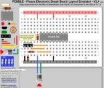
the only thing missing from my download board is the rest button, as i presume it is a jumper from pin 4 to ground?
the board is on a breadboard, ive remade it twice, and its been checkd over by a classmate.

so please, any ideas? this is first time with the 18X
___________________________________________________


Question 2) - Using Pulsin commands.

im going to use the Pulsin command to count the pulse width coming out from the ECU of the car.
what would be a safe/suitable voltage to use, to read the pulse width with?
(i can not find this in a manual)


thanks very much!
Snowy
 
Last edited:

Andrew Cowan

Senior Member
The 255 error usually indicates a problem with the power supply. Have you tried putting smoothing (100uF) and decoupling (100nF) capacitors across the power supply of the PICAXE?

Is the PSU from a computer, or a plug in transformer? I'd recommend trying it three AA batteries.

Also serin will not count the pulses - you need the COUNT command, or PULSIN to measure the pulse width.

A
 

Snowghost

New Member
The 255 error usually indicates a problem with the power supply. Have you tried putting smoothing (100uF) and decoupling (100nF) capacitors across the power supply of the PICAXE?

Is the PSU from a computer, or a plug in transformer? I'd recommend trying it three AA batteries. A
Its one of the bench top power supplies that we use at Tech, i beleave they are pretty good. but will give still give that a go.

Also serin will not count the pulses - you need the COUNT command, or PULSIN to measure the pulse width. A
your dead right. i made a mistake there (*edited*) i am in fact using the Pulsin.
thanks Andrew.
 

Charliem

Senior Member
Snowghost,

For your voltage levels for reading the input you want no more than 5 volts going into the picaxe.Do you have another chip you can try?
 

Dippy

Moderator
Snowghost;

I'm not going to prattle on about safety in vehicles.
Not am I going to prattle on about well suppressed/protected power supplies in vehicles.
And I'm definitely not going to give you the usual Doom & Gloom warnings with novices installing electronics modules in their cars.

So....

As said above the pulse voltage should not exceed 5V.
Use a 'scope to check pulse from ECU (assuming it is a standard nice little 'square' pulse).
You should also protect the PICAXE and your ECU by using a resistor of a medium value, say 2K2 or 4K7 - this could help prevent accidents. Some people may include a zener to provide extra protection.

If the pulse is over 5V you should use a potential divider to step the voltage down (aka Level Shift).

Downloading.
If your wiring is right and your power supply is right and your PC is Ok then downloading should be a breeze.
Is your PICAXE stuck on a hairy old breadboard?
I always recommend people buy the cheapest PICAXE kit so that the download circuit is done for them - that removes one 'variable' from the equation.

I'm afraid that 'believing' something is good is not good enough.
If using a PSU it should be providing a nice smooth 5V.
Also, unless there is current limiting on your school PSU, you're running a risk of causing damage due to incorrect wiring.
Have you had a little error or two during building?
 
Last edited:

hippy

Technical Support
Staff member
Your circuit looks okay to me.

I wish more people would use it to show what they are doing or should be doing!

The usefulness of PEBBLE really depends on what PEBBLE is being used for.

For "Is this right?", PEBBLE alone is not so good except for simple circuits when we can polish crystal balls and make a good guess as to how the circuit should be.

The "Is this right?" is asking two things; 1) have I got my circuit right, 2) have I wired my board to implement the circuit correctly. The second cannot be answered unless the first is known, and that usually requires a circuit diagram.

When a PEBBLE layout is presented by itself, to comment on its accuracy requires the circuit diagram to be deduced from the layout and that may require effort which people are not willing to put in.

Where PEBBLE really scores is in "and this is what it should look like" for people duplicating a breadboard layout which is known to work.
 

dmaxben

Member
Ridiculously old thread, but id rather try asking here than starting a whole new thread of the same topic.

What was the solution to the problem? Im working on a similar project for use on a dyno test stand, not in an actual vehicle though. Im going to be using the tach output from a factory GM ECM to control a PICAXE program/display. And then of course the "COUNT" command on the PICAXE. The only thing the service manual tells me is that the output signal wire that goes from the ECM to the instrument cluster is "2 pulses per revolution". I would assume that means its a normal square-wave signal that transitions cleanly from V+ to ground X times/second based on RPM. Im doing more research now to see what voltage it rises to. If I find out that it rises above 5v (Vss/Vdd to the PICAXE), then Ill try using a resistor and/or voltage divider to make sure that when the ECM pulls the tach signal wire "UP", it does not go above the PICAXE 5v power input.

I assume thats basically all that I will need to do as far as an "interface circuit" from the factory ECM to the PICAXE... Not sure if the input pin on the PICAXE should have the normal pulldown resistor in addition to any clamping circuit, or if the clamping circuit/output wire from the ECM already has the proper pulldown/circuit so that the wire is never just left "floating"....

Ben
 

dmaxben

Member
Just figured I would reply that I figured it out! I used a 2N3904 transistor, a 4.7k resistor, and a 10k resistor. Very simple circuit. Tapped directly into the tach-signal wire that goes to the [factory] instrument cluster. The factory tach/instrument cluster still works perfectly, even with the PICAXE tapped into the tach-signal wire.

I used the "count" command, and then had the PICAXE do some simple arithmetic, and now it outputs the proper RPM as a number (w2) in the debug terminal! I compared it to the actual reading of engine RPM as shown by the factory scan tool that reads RPM from the ECM over the databus, and my simple PICAXE circuit/program is accurate, within 10rpm or so. :)

Code:
main:
pause 25
count c.4, 125, w1
let w2=w1 * 225
debug
goto main
 
Top