Hemi345
Senior Member
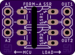
I have a motorized sit/stand desk and one of the buttons quit working on the control. The control has an RJ11 connector with 4 pins. 2 pins (soldered together in the photo below) show 24VDC when connected to either of the other two pins with my multimeter. When either of the other two pins are shorted to the 24V, the desk moves up or down.
So one of my complaints with this system over the years has been the need to hold the button down to move up the desk up or down. I wish I could have afforded the more expensive model to get the preset positions, but whatever. The easy answer to fix this is buy a new control panel - but where's the fun in that. The other option is to snip the end off the RJ11 cable and add a switch - solves the issue with holding the buttons down while the desk moves but still doesn't give me preset positions. Option three, pimp out my desk by mounting an ultrasonic ranger finder under there, use a PICAXE to program in my own preset height adjustments and some MOSFETs to signal the motion.
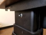
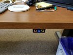
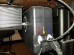
I don't know the circuit design for the desk so I'm making an assumption that the 2 pins that are connected to the buttons have pull downs on them. When shorted to 24V, the relays near the motors activate. The relays and such are packed away inside one of the motor assemblies (photo below) so trying to take it apart to see how it works would be a very involved process (for one, I'd have to clean off my desk to unload the tension and that's a feat in of itself haha). I could tap into the 24V cable (red arrow) to supply the PICAXE with power but was just wondering if I could have a more tidy setup by using just the RJ11 cable (yellow arrow) to power my little project too (since one of the pins would always be low/gnd). Just FYI, the blue arrow is pointing to a cable that connects left motor to right motor. Thoughts on this?

So one of my complaints with this system over the years has been the need to hold the button down to move up the desk up or down. I wish I could have afforded the more expensive model to get the preset positions, but whatever. The easy answer to fix this is buy a new control panel - but where's the fun in that. The other option is to snip the end off the RJ11 cable and add a switch - solves the issue with holding the buttons down while the desk moves but still doesn't give me preset positions. Option three, pimp out my desk by mounting an ultrasonic ranger finder under there, use a PICAXE to program in my own preset height adjustments and some MOSFETs to signal the motion.
I don't know the circuit design for the desk so I'm making an assumption that the 2 pins that are connected to the buttons have pull downs on them. When shorted to 24V, the relays near the motors activate. The relays and such are packed away inside one of the motor assemblies (photo below) so trying to take it apart to see how it works would be a very involved process (for one, I'd have to clean off my desk to unload the tension and that's a feat in of itself haha). I could tap into the 24V cable (red arrow) to supply the PICAXE with power but was just wondering if I could have a more tidy setup by using just the RJ11 cable (yellow arrow) to power my little project too (since one of the pins would always be low/gnd). Just FYI, the blue arrow is pointing to a cable that connects left motor to right motor. Thoughts on this?