Serial to RS485 problems

hax

New Member
Hi all,

I have built a network of picaxe 14M chips that communicate between each other through a MAX487 RS485 chip.

They all work nicely and I can "see" the messages being sent and received using a terminal program.

However, when I use a PC to send an instruction through the 485 bus, the Picaxe chips don't respond.

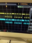
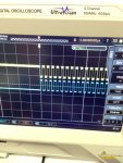
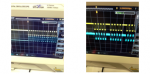
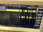
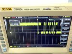
So I thought this was a timing issue, and took out my nice new oscilloscope to investigate...... Well it seems that the timing is correct, but there is a difference that appears between characters..... Attached are two images. Image "3" is the picaxe sending a "GVC" ascii string, and "4" is the PC sending the same string. There are differences every 8 bits. Is this a timing issue between letters?
 

Attachments

Paix

Senior Member
When you transmit with the PC, does the PC associated RS485 transceiver have the pin 3 "DE" line asserted high and are you scoping the transceiver pin 6 "A" line?

You don't mention where you were monitoring with your scope. Inversion of data to make it good should be on the TTL side of an interface and not by swapping "A" and "B" lines, but I guess you figured that much out already.

Nice scope, noisy signal :)

I'm up to order some Black Firiday bits before my activities become of interest to she who sleeps presently. Hope you find the problem dead quick and let us know what it turns out to be.
 

hippy

Technical Support
Staff member
It looks to be related to parity / stop bits but it's hard to analyse when it's not clear where you are measuring in the circuit. Is it an issue of what is going into the RS485 drivers or an issue of what's then put on the RS485 bus ?

It's hard to check anything without knowing which PICAXE is being used, the code doing the sending, and without a full circuit diagram.

Can you confirm that the image on the left (4) is what the PC put out, the image on the right (3) is what the PICAXE puts out.
 

hax

New Member
For both measurements the scope was connected to a pin of a picaxe 14m which receives the commands. So the reading is taken after the max486 chip. Ill try using hserin and hserout but so far I have used serin and serout commands. The noise would be due to the lead that I am using on the scope.
 

hippy

Technical Support
Staff member
For both measurements the scope was connected to a pin of a picaxe 14m which receives the commands. So the reading is taken after the max486 chip.
We would recommend monitoring what the sending PICAXE is putting out on one trace and what the receiving PICAXE gets on the other trace to see if the signal is correctly replicated or not.
 

Paix

Senior Member
That would be the transceiver pin 1 "RO" then that the reading is from unless you have something else between it and the receiving Picaxe pin.
 

g6ejd

Senior Member
Have you set your PC serial port up correctly. The polarity of the signal looks ok to me.
It looks like parity is on by the bit count. Can you repeat the exercise with a capital R or Y or R then space. R or Y alternates the bits 1 0 1 0 etc. space is just a single bit, that will help the bit count.
 

Paix

Senior Member
It's ASCI/ITA5I Dave, not Baudot/Murray/ITA2, but I know what you are thinking about . . . Start bit to right of the display? Paper tape readers (green key wizards) tend to think left to right, so I occasionally(?) confuse myself.

ASCII capital U, 85 Decimal or 55 Hex, steadymarking stopbit 01010101 startspace steadymarking (character reading right to left).

Ian, G0PAi
 

hax

New Member
OK I'm getting closer to figuring this out.... Image "5" was taken when the PC was sending a "UUU" ascii string. The blue line is the PC serial out pin and the yellow line is what the picaxe is receiving on the serin pin. Nice up and down traces....

Image "6" was taken where one picaxe is sending "UUU" and the other is receiving it. As you can see, there is a problem at the end of each letter. The last bit is slowing down/being currupted/has a problem with the stop bit?


Im reading the serout instructions, and they say that data output is 8 data bits, no parity, 1 stop bit. This is the same as what the PC is set to..... so why the difference? This isn't anything to do with the 485 bus as I am reading the strings straight from picaxe serin and serout pins.....
 

Attachments

hax

New Member
OK, hserout produces the same wave form as the PC. No problems with the last bits. So I am led to believe that the serout command on the 14M2 chip takes a while to move to the next letter, hence the delay and timing issue....

Now I am trying the hserin command and I have come up with what appears to be a huge limitation. It seems on the M2 parts, you can only read two bytes at a time....The problem is that I need to read a string such as: "GVC,9999,W11".

The "GVC" is the qualifier, the "9999" is the address and the "W11" is the info on whether a valve should open or close.... It seems that the M2 parts simply won't work for this purpose :-(
 

hax

New Member
Is there a workaround for this? With only receiving two bytes at a time, there seems to be no way of using 3 letter qualifiers let alone receiving a decent amount of variables. From what I understand M2 parts can't write to the scratchpad, hence processing has to happen on the fly?
 

Paix

Senior Member
Haxby, you are difficult to follow and are jumping about like a cricket.
Do me a favour, instead of sticking me with two pictures of your screen at odd angles which screws with my brain at the best of times, stick them together so that I can see them both the right way up side by side at the same time.
View attachment 12999
View attachment 13000
From what you have shown, I understand that the character is displayed with the start bit on the left, after a steady marking condition. Please confirm.

That being the case, then What do you imagine hand sent characters would look like? Read it as minimum 1 stop bit. From what I see, both pictures are good, but the character rate of the PICAXE is slightly slower. The rate, not the speed. The data is also True, with an idle mark high condition.

So, given that your data is all the same way up, where does that leave us. I'm answering the thread from the point of your last scope images and ignoring the rest, because you are outstripping my thought process and flapping around like a kipper.

Where in the world are you by the way? It helps to know when to look for responses etc. I am guessing that it is the US because of the time of your posting.

So where are we? I don't know what you know or don't and you have the problem, not me. So if you can wise me up a little bit then I can help. If not, then I too have other things that I can be doing.

You originally said that you were transmitting from your PC and the characters weren't being received by your RS485 connected PICAXE boards.

I assume that when sending from the PC, you scoped the bus "A" line, as I asked you previously? And the PC transmit data was there? And it would be on any and all of your PICAXE boards appearing on both pins 6 and 1 of the relevant RS485 transceiver?

Please make it as easy to help you as possible. :)
 

hax

New Member
Hi Paix, what's a kipper?

But seriously, apologies if I sound confusing, I'm just narrowing down the problem. I have attached two images (the right way up this time).... Concentrate on the yellow trace only. This is measured on the pin of the picaxe receiving the serial string.

In image 7 you see what the picaxe receives from the PC when the PC sends "UUU".

In image 8 you see what the picaxe receives from another picaxe when it sends "UUU".

There should be no difference, as the baud rate, stop bits, and parity are the same, yet there is quite a long pause between letters when the picaxe is sending the string, and no pause at all when the PC is sending the string. This is the problem in a nutshell.... The receiving picaxe can't keep up, and won't receive the string properly from the PC.

Hence, I have since changed to using the hserin and hserout commands, but as I am using a 14M2, there seems to be no scratchpad available for hserxxx commands, and there seems to be no way of parsing a string from the PC. (Unless I have missed something)

I want to send a command from the PC to the picaxe in the form of eg. GVC,9999,REA

Where:
GVC = qualifier
9999 = address of picaxe on the bus
REA = read values (or some other action command)


Now picaxe to picaxe communication works just great on the bus, but PC to picaxe communication does not work!
 

Attachments

Goeytex

Senior Member
As you have discovered, there is extra space between bytes when using serout. This is intentionally coded in the firmware and generally does not cause problems. I'll let others explain why the extra space was added.

There is no reason that you cannot use hserout for sending and serin for receiving qualifier & multiple bytes. In the hsersetup mode, make bit 4 a "1". .. eg. < hsersetup B9600_8 , %10000 >

This should disconnect Pin B.1 from the hardware UART, disable hardware hserin, and allow the pin to be used for general I/O or for serin.

What clock speed are you using for the Picaxe ? What baud rate for serial data?
 

hax

New Member
Speed is setfreq m8 on the 14M2.

Baudrate is 9600.

Serin certainly doesn't work if its coming from a PC, which is contrary to what you are suggesting? Yet it does work when another picaxe sends the commands. This suggests that the space between characters is required by both the sending and receiving picaxe.....


I just want to confirm 100% that there is no other way of receiving multiple bytes (say 10 or so) in one hit with the hserin command?

Thanks all for the suggestions.
 

Goeytex

Senior Member
Serin certainly doesn't work if its coming from a PC
It certainly works fine for me. I suggest trying M16 instead of M8 to reduce Picaxe Processor overhead time.
Adjust serin command accordingly. The combination of 9600 baud and 8Mhz does not leave much room for needed processing time with software serin.

The only way you can get > 2 bytes with hserin is to use an X2 Picaxe.
 
Last edited:

hippy

Technical Support
Staff member
There should be no difference, as the baud rate, stop bits, and parity are the same, yet there is quite a long pause between letters when the picaxe is sending the string, and no pause at all when the PC is sending the string. This is the problem in a nutshell.... The receiving picaxe can't keep up, and won't receive the string properly from the PC.
That's about the sum of it; SERIN needs an inter-byte gap to work properly. HSERIN doesn't need inter-byte gaps, but you need to use an X2 to automatically move data into the scratchpad, or run fast enough to keep HSERIN available for further data.

Alternatively; generate the data from the PC such that there are inter-byte gaps so SERIN can be used.
 

Paix

Senior Member
I don't suppose that the PC can be configured to generate 2 stop bits? That would possibly be simpler than parsing the strings to send in a loop and sending them singly with a slight pause between.

I too tend to think about automatic transmissions at full tilt and think that the generation of one stop bit is a bit short. In effect, what has been said is that 8bits no parity one stop bit and a slight pause between characters is recommended. On the receive side the receiver is ready for the next character (in theory) less than half a bit after the 8th bit has been transmitted. Alas, we are not using dedicated receivers, but processors that we also expect to do other things and so the situation is slightly less than ideal, so that extra thought has to go into the process.

Had you said at the outset that the levels were all good etc. and that the transmit character rate of the PC was apparently greater than the transmit rate of the PICAXE chip, we could have saved a lot of time.
Z3.png
Contrast how much easier it is to compare two images side by side, rather than viewing alternately.
= = =
Ho ho, the size not withstanding - I got that wrong :)
 
Last edited:

hax

New Member
Very interesting:

I increased speed to setfreq m16 and repeated the oscilloscope tests, I also tried SEROUT 4800 baud. You would assume that with faster processing power, the gap would be smaller, however tests show that the "gap" does not change when using a faster frequency, which leads me to believe that it is artificially padded for uniformity across all processor speeds.

Yet at m16, the SERIN command works much better, and it is "clever" enough to receive strings from the PC and from other picaxes.

Problem solved and lesson learnt: I will use the fastest frequency available from now on even if using slower baud rates. The faster frequency must enable a better sample rate for the data stream.
 

Paix

Senior Member
That's good news.

It's always a source of irritation that the overhead can get in the way when using serial comms. Perhaps we have been spoiled by faster processors, such as the PCs of recent years and tend to overlook that the PICAXE resource is both shared and finite.

Sorry, if I was a little terse trying to elicit info from you. I should have shown a lot more patience.

I'm impressed with the scope and am currently looking at the Rigol 1052E or something similar myself. Unfortunately there are a lot of devices out there that have a default 9600 baud and so stretch the capabilities of some chips. Looking back though, even mainframes used to have mini computer communication front ends, so perhaps we have lost sight of the fact that the communication process is occasionally best devolved to dedicated devices.

Wishing you every success with the project. Is it a work or hobby venture?
 
Top