HaraldWien
New Member
Servus from Vienna!
This is probably the 400001 serial display driver, which is presented here. But for me he is the first one I've built myself ;-)
Realized I have the whole thing with a PICAXE-20X2. To test as master I have also taken a 20X2 because my 20M2 was too small (program-overflow).
First, the hardware - ie the circuit diagram:
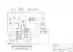
TinyCad-File: https://www.dropbox.com/s/0txoivnkou6u97m/HaraldsLcdHandler.dsn?dl=1
The software you can watch / download here:
LCD-PICAXE: https://www.dropbox.com/s/5fc8c8qofxai5uy/HaraldsLcdHandler.bas?dl=1
MASTER-uC: https://www.dropbox.com/s/my4l982sz61tze1/HaraldsLcdHandlerTest.bas?dl=1
And then of course there's another video that the expiration of the test program on the LCD display. All who want to know exactly how it works, look at the two programs.
So here's the link to the video:
[video=youtube_share;r141uURxxeY]http://youtu.be/r141uURxxeY[/video]
 View attachment 17348
First I wanted to make a normal 4-bit-mode control of the display and as usual the R/W-line "grounden". Only describe the LCD display.
In testing I have but pretty quickly realized that I get a timing issue and that the LCD PICAXE with reading the data from the master PICAXE (hereinafter referred to as master-uC - because it must indeed be a PICAXE) and the processing thereof does not comply. Again and again, characters were swallowed. So read a byte and equal process took too long.
One thing was clear, necessarily from the master PICAXE I wanted to send character strings rather than individual characters with "SEROUT". That was the point of the exercise, else would I yes again all over the i2c bus can make, like my temperature monitor.
Therefore, this LCD driver now operates synchronously and asynchronously not, according to the following pattern:
In the PowerOnPhase will make sure that the LCD-PICAXE is ready first.
This is now waiting for her RxD port for commands and texts, which sends the master-uC his hand over the TxD port. These character strings in a buffer that is 96 digits long, parked. Each character string is terminated by the master-uC with a 0xFF characters. This signals to the LCD-PICAXE that now the buffered character can be processed. Is the LCD-PICAXE finished processing the string, then sends them on their TxD port from a 0xFF as confirmation that the processing technology has been made and that it now expects new orders and texts. The master-uC in turn sets off immediately after sending the end character 0xFF to his RxD port and waits for the ready signal (0xFF) of the LCD-PICAXE.
About the dialogue RxD and TxD lines, which now are indeed present in two uC's, can now follow the same pattern also return data, are transmitted from the LCD- to the master PICAXE-uC. For example, the master-uC of the LCD-PICAXE, which over the i2c bus has access to the RTC-chip DS1307 requesting time.
The advantage of this synchronous processing is that you now do not have to work with esteemed "pause" commands, but exactly then continues in the sequence, when the completion message of the LCD-PICAXE (0xFF) arrives.
The LCD-PICAXE works consistently as a "slave". That is, it performs actions as directed by the master. ONLY exception is the automatic switch off the LCD-LED lighting.
I have also experimented that the LCD-PICAXE switchable updates automatically date and time on the display. That was me but then too uncertain. Here I would after a timeout scheme perform operations (date + time read from RTC, check, edit and write in the LCD_DDRAM) whose duration are not estimated. I wanted so have an automatic function, then I would settle them in the future in the master-uC.
The following commands and functions can run the LCD-PICAXE:
All characters with character codes from 0x00 to 0xF9 (0-249) can be regarded as a normal character to be displayed. Higher-order mark (0xFA - 0xFE; 250-254) are used as command characters. 0xFF (255) is used exclusively as a termination character. The only exception here is the character with the code 0xFC (252) - our dear umlaut U and indeed in its small form "ü" .
With the character 0xFE (254) signals that then the following character as a command character of the LCD-function catalog 1: 1 must be passed to the LCD-display.
Special Functions
Special functions are initiated by the 0xFA character (250). Depending on the function then data must be sent or picked up from the master-uC (see code).
In test mode were both the LCD- PICAXE and the MASTER-PICAXE, connected to the i2c bus.
From both you can easily read and write data from the RTC-chip DS1307.
As a user, so it can choose whether to read/write the RTC data in the master-uC directly from the DS1307 chip, or whether you can do that from the LCD-PICAXE. Read or write the data on the RxD/TxD lines.
I hope, my words arrive you as i mean. Always kindly and without harm.
Have a nice xmas-time.
Harald
This is probably the 400001 serial display driver, which is presented here. But for me he is the first one I've built myself ;-)
Realized I have the whole thing with a PICAXE-20X2. To test as master I have also taken a 20X2 because my 20M2 was too small (program-overflow).
First, the hardware - ie the circuit diagram:
TinyCad-File: https://www.dropbox.com/s/0txoivnkou6u97m/HaraldsLcdHandler.dsn?dl=1
The software you can watch / download here:
LCD-PICAXE: https://www.dropbox.com/s/5fc8c8qofxai5uy/HaraldsLcdHandler.bas?dl=1
MASTER-uC: https://www.dropbox.com/s/my4l982sz61tze1/HaraldsLcdHandlerTest.bas?dl=1
And then of course there's another video that the expiration of the test program on the LCD display. All who want to know exactly how it works, look at the two programs.
So here's the link to the video:
[video=youtube_share;r141uURxxeY]http://youtu.be/r141uURxxeY[/video]
View attachment 17348First I wanted to make a normal 4-bit-mode control of the display and as usual the R/W-line "grounden". Only describe the LCD display.
In testing I have but pretty quickly realized that I get a timing issue and that the LCD PICAXE with reading the data from the master PICAXE (hereinafter referred to as master-uC - because it must indeed be a PICAXE) and the processing thereof does not comply. Again and again, characters were swallowed. So read a byte and equal process took too long.
One thing was clear, necessarily from the master PICAXE I wanted to send character strings rather than individual characters with "SEROUT". That was the point of the exercise, else would I yes again all over the i2c bus can make, like my temperature monitor.
Therefore, this LCD driver now operates synchronously and asynchronously not, according to the following pattern:
In the PowerOnPhase will make sure that the LCD-PICAXE is ready first.
This is now waiting for her RxD port for commands and texts, which sends the master-uC his hand over the TxD port. These character strings in a buffer that is 96 digits long, parked. Each character string is terminated by the master-uC with a 0xFF characters. This signals to the LCD-PICAXE that now the buffered character can be processed. Is the LCD-PICAXE finished processing the string, then sends them on their TxD port from a 0xFF as confirmation that the processing technology has been made and that it now expects new orders and texts. The master-uC in turn sets off immediately after sending the end character 0xFF to his RxD port and waits for the ready signal (0xFF) of the LCD-PICAXE.
About the dialogue RxD and TxD lines, which now are indeed present in two uC's, can now follow the same pattern also return data, are transmitted from the LCD- to the master PICAXE-uC. For example, the master-uC of the LCD-PICAXE, which over the i2c bus has access to the RTC-chip DS1307 requesting time.
The advantage of this synchronous processing is that you now do not have to work with esteemed "pause" commands, but exactly then continues in the sequence, when the completion message of the LCD-PICAXE (0xFF) arrives.
The LCD-PICAXE works consistently as a "slave". That is, it performs actions as directed by the master. ONLY exception is the automatic switch off the LCD-LED lighting.
I have also experimented that the LCD-PICAXE switchable updates automatically date and time on the display. That was me but then too uncertain. Here I would after a timeout scheme perform operations (date + time read from RTC, check, edit and write in the LCD_DDRAM) whose duration are not estimated. I wanted so have an automatic function, then I would settle them in the future in the master-uC.
The following commands and functions can run the LCD-PICAXE:
All characters with character codes from 0x00 to 0xF9 (0-249) can be regarded as a normal character to be displayed. Higher-order mark (0xFA - 0xFE; 250-254) are used as command characters. 0xFF (255) is used exclusively as a termination character. The only exception here is the character with the code 0xFC (252) - our dear umlaut U and indeed in its small form "ü" .
With the character 0xFE (254) signals that then the following character as a command character of the LCD-function catalog 1: 1 must be passed to the LCD-display.
Overview of functions- Function-251 (0xFB): Send LCD-DDRAM data to master-uC. With this function it is possible to read an entire 80-digit "LCD screen" or just parts of it in the master-uC. If, for example, useful if one wants to avoid redundant formatting operations.
- Function-253 (0xFD) -0xx: display a text module from the internal EEPROM area of the LCD PICAXE on the LCD panel. The EEPROM area of the PICAXE-20X2 used comprises 255 characters, which can be used for any length of text blocks (max. 80 characters per text block).
- Function-253 (0xFD) -1xx: Loading a text module from the master-uC in the internal EEPROM area of the LCD-PICAXE.
- Function-253 (0xFD) -2xx: Send a text module from the internal EEPROM area of the LCD-PICAXE to the master-uC. This means that text blocks can not only appears on the LCD-display, but also be requested from the master-uC.
Special Functions
Special functions are initiated by the 0xFA character (250). Depending on the function then data must be sent or picked up from the master-uC (see code).
- Special-Function-0: turn off the LCD backlight.
- Special-Function-1: LCD backlight on.
- Special-Function-2: LCD illumination switch (toggle - from ON to OFF and vice versa).
- Special-Function-3: LCD illumination switch to automatic. The following characters, the duty (1 to 255 seconds) will be announced.
- Special-Function-4: Turn off the LCD backlight automatic.
- Special-Function-5: Load LCD-DDRAM data in cache. If, for Example information or error messages, and then again, the original content will be displayed on the display, then is this, and the following special function very useful.
The LCD-PICAXE uses these special functions 5 and 6 of course.
If, for example, at the date of examination (WARNING! No leap year detection installed) error is detected, then the current "screen" saved, the error message and then reappear the originally Screen content.
- Special-Function-6: Load the LCD-DDRAM data from the buffer back into the LCD DDRAM memory.
- Special-Function-10: Display Weekday abbreviation on the LCD panel.
- Special-Function-11: Display Weekday name on the LCD panel.
- Special-Function-12: Time (HH: MM) show on the LCD display.
- Special-Function-13: Time (HH: MM: SS) show on the LCD display.
- Special-Function-14: date (TT.MM.JJ) show on the LCD display.
- Special-Function-15: date (TT.MM.JJJJ) show on the LCD display.
- Special-Function-16: day + date + time (XX TT.MM.JJJJ HH:MM) show on the LCD display.
- Special-Function-17: day + date + time (XX TT.MM.JJ HH:MM:SS) show on the LCD display.
- Special-Function-20: Send Weekday abbreviation to master-uC.
- Special-Function-21: Send weekday designation of master-uC.
- Special-Function-22: Time (HH: MM) send to master-uC.
- Special-Function-23: Time (HH: MM: SS) send to master-uC.
- Special-Function-24: date (TT.MM.JJ) send to master-uC.
- Special-Function-25: date (TT.MM.JJJJ) Send to master-uC.
- Special-Function-26: day + date + time (XX TT.MM.JJJJ HH:MM) send to master-uC.
- Special-Function-27: day + date + time (XX TT.MM.JJ HH:MM:SS) send to master-uC.
- Special-Function-100: date + time (decimal / bin) load in RTC-chip.
- Special-Function-101: date + time (decimal / bin) send from RTC-chip to master-uC.
- Special-Function-110: square wave control code download (SQW) in RTC-chip.
- Special-Function-111: square wave control code (SQW) send from RTC-chip to master-uC.
- Special-Function-201: View texts from the "table" area on the LCD screen. In the "table area" are indeed already has 200 bytes in the current program state. But the rest of the space, as well as the standard periodic texts can be used by the user.
- Special-Function-202: Send texts from the "table" area to master-uC.
In test mode were both the LCD- PICAXE and the MASTER-PICAXE, connected to the i2c bus.
From both you can easily read and write data from the RTC-chip DS1307.
As a user, so it can choose whether to read/write the RTC data in the master-uC directly from the DS1307 chip, or whether you can do that from the LCD-PICAXE. Read or write the data on the RxD/TxD lines.
I hope, my words arrive you as i mean. Always kindly and without harm.
Have a nice xmas-time.
Harald