SD Card Troubleshooting

ylp88

Senior Member
I've had a goal to at least attempt some PICAXE-SD card communications for some time now and after looking at some previous attempts (acknowledgements to Hippy and DPG) and despite the problems most people seem to have had, I decided to have a shot at it anyway since I have some time during my Uni break.

To that end, I managed to use a PICAXE-28X1 to do some simple initialisation, reading and writing to a small range of different SD cards (I have a 16MB Canon, 128MB Generic, 256MB Sandisk, 1GB Sandisk Ultra II, 2GB Sandisk Ultra II Plus and 2GB Generic). So far, the results have been promising in that I have successfully managed to initialise all the cards except for the 2GB cards and I had and managed to write a 512 byte sector to each of them, neglecting anything to do with any sort of file-system: FATxx etc. These results were confirmed using a SD card reader and appropriate software on my desktop computer.

I did run into a couple of problems that I've not yet had the time to fully investigate and could do with some suggestions. Before I do that, I'll just give a quick background of my setup:

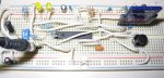
The cards are socketed into a breadboard and connected via SPI to the PICAXE (28X1, FW.A0) with 100k pull-up resistors (I've also tried 47k and 82k). Both the card and PICAXE are powered from a regulated 3.3V supply with 100uF bulk capacitance and two 0.1uF capacitors near the SD card's power pins and one near the PICAXE's supply pins. I've run all my tests using both 4MHz and 8MHz internal oscillators as well as 4MHz and 16MHz external resonators (with the appropriate setfreq commands). Operations always used spislow mode but all results were also reproducible if spimedium was used after initialisation.

To the "problems" at hand:

1) Why could I not initialise the 2GB cards? Perhaps of relavance, I assume that both of them are not SDHC cards as I use both of them in my PDA which I do not believe supports SDHC cards.

2) As mentioned, spimedium worked if switched to after the cards were initialised (i.e. when I begin my read/write tests). spifast was strictly no-go with the PICAXE timing out after ~2.3 seconds and resetting itself. Why?

Interestingly, I couldn't get spifast to work with my SPI interfaced MP3 decoder chip (VLSI VS1002D) either, but spislow and spimedium worked fine...

3) Although the data was successfully written to all the cards which could be initialised, I have had problems reading the data back from only the 16MB Canon; all the other cards report the correct data back. Regardless of the data stored, the data received turns to:

xx xx xx xF FF xx xx xx xx xx xx xF FF xx xx xx ...

Just to clarify, the first three bytes are read correctly (the first three sets of "xx". The upper (4-bit) nibble of the next byte is received correctly then 12 high bits are received (thus three hexadecimal digits of "FFF"). The cycle then repeats with a period of 8 bytes with the rest of the bits until the next cycle read/reported correctly.

As I said, this only occurs with only ONE of my SD card while all the others report the data back perfectly. First thing that comes to mind is some "card not to specification" thing, but the periodicity and reproducibility makes me wonder.

Anyhow, any and all suggestions to the above points are appreciated in advance and will be entertained as time permits. Thanks!

ylp88
 

hippy

Technical Support
Staff member
I'd say you were further along than anyone else here so not sure how much help you'll get. Google may be your last hope.

For the 16MB Cannon which doesn't work fully, it could have something to do with a smaller block size or along those lines. Can you fill the card with known data from a PC ("ABCDABCD...", read the card back and see if you get any meaningful data ? That will help narrow it down to being a read or write issue.

For the 2GB, it's on the cusp of being old-style or new SDHC. Again it could be that 2GB are subtley different to those smaller. This may help, and worthwhile taking a copy for future reference any way, or it may just be an irrelevancy ...

http://www.samsung.com/global/business/semiconductor/products/flash/downloads/applicationnote/4gb_mmc_application_note_200606.pdf

As to the faster SPI modes, it could perhaps be an imbalance on the SDA/SCK lines ? Maybe a tweaking of pull-ups ?

'Fraid I'm really just guessing. I'm impressed though, well done.
 

ylp88

Senior Member
For the 16MB Cannon which doesn't work fully, it could have something to do with a smaller block size or along those lines. Can you fill the card with known data from a PC ("ABCDABCD...", read the card back and see if you get any meaningful data ? That will help narrow it down to being a read or write issue.
I do believe that the data is being written correctly as I can read the expected data using my computer's card reader. The problem seems to arise when reading the data back off the card. At the moment, it is my most interesting issue but since it only occurs on only my smallest capacity card, I probably won't look into it too deeply unless I have the time.

As to the faster SPI modes, it could perhaps be an imbalance on the SDA/SCK lines ? Maybe a tweaking of pull-ups ?
I did try a range of pull-ups although I only stayed within the spec that I could find - 50k to 100k, from memory. I'll give some other values a try since you mentioned it though. With any luck, perhaps it might even fix the problem I'm having with my 16MB card. The suggestion sounds even better when I think that since I am running the PICAXE at 3.3V, the input logic levels might be a bit more limited that if the chip was running at a nominal 5V. This is certainly something I'll be looking at.

'Fraid I'm really just guessing. I'm impressed though, well done.
Well, I'm sure your guess is better than mine! And thanks for your approval. You can rest assured that if I managed to get some good results (which I don't think I'm too far off, although I shouldn't speak too soon!) I'll publish it here for all of you to peruse.

Thanks for the suggestions, Hippy.

Any other suggestions are still more than welcome!

ylp88
 

ylp88

Senior Member
With My work on the VDrive2 I also found zero functionality with SPIFast on the 28X1 vA.1
This is actually one of the main reasons why I am trying to use an SD card at the moment. The prototype MP3 player I made tried reading the MP3 from a USB drive via the VDrive device, however after failing to be able to use SPI mode, I was using serial and the PICAXE's HSER commands. Of course, the bandwidth was very poor and the audio was all broken up (although still recognisable is you knew what song was playing at the time).

The downside to using this approach is that I very much doubt that I'll be implementing any proper filesystem such as FAT16 or FAT32 which means that my system can't use cards loaded from the desktop computer. There are some other issues (and some benefits I can think of) but I'll get to them once I am satisfied with the SD card code I have.

ylp88
 

profmason

Member
Please post your code! Also a schematic if you have one. I just pulled the SD card interface off the shelf of "Stuff that doesn't work" and would love to give it another shot. It has been sitting there since I spent some time on it after the 28X1 came out. I have about 30 32Mb SD cards sitting a box waiting for the data logger that uses them to get built.

Till then I am still using the much maligned Vdrive2.

thanks!
 

ylp88

Senior Member
Please post your code! Also a schematic if you have one. I just pulled the SD card interface off the shelf of "Stuff that doesn't work" and would love to give it another shot. It has been sitting there since I spent some time on it after the 28X1 came out. I have about 30 32Mb SD cards sitting a box waiting for the data logger that uses them to get built.

Till then I am still using the much maligned Vdrive2.

thanks!
Here's my code so far. I only really worked on the code for a day or so and as a consequence, it's pretty messy and it's not commented. I'm somewhat busy at the moment but if I can find the time, I'll edit the code and put in some comments. Otherwise, the SERTXD commands should be relatively self-explanatory to help you understand what is going on.

Code:
setfreq em4

symbol CS = 0

sertxd(13, 10, "Start:", 13, 10)

HSPISETUP spimode00, spislow

pause 1000

sertxd("Dump SPI", 13, 10)
high CS
for b0 = 1 to 10
	HSPIOUT($FF)
next b0
low CS
for b0 = 1 to 2
	HSPIOUT($FF)
next b0

sertxd("CMD0... ")
HSPIOUT($FF, $40, $00, $00, $00, $00, $95, $FF)
HSPIIN(b0)
sertxd(#b0, 13, 10)

retryinit:

sertxd("CMD55... ")
HSPIOUT($FF, $77, $00, $00, $00, $00, $95, $FF)
HSPIIN(b0)
sertxd(#b0, 13, 10)

sertxd("CMD41... ")
HSPIOUT($FF, $69, $00, $00, $00, $00, $95, $FF)
HSPIIN(b0)
sertxd(#b0, 13, 10)

if b0 <> 0 then retryinit

sertxd("CMD16... ")
HSPIOUT($FF, $50, $00, $00, $02, $00, $95, $FF)
HSPIIN(b0)
sertxd(#b0, 13, 10)

high CS
sertxd("Card initialised!", 13, 10)


' ******************************************

if pin6 = 1 then readsd

low CS
sertxd("Write data:", 13, 10)

sertxd("CMD24... ")
HSPIOUT($FF, $58, $00, $00, $00, $00, $95, $FF)
HSPIIN(b0)
sertxd(#b0, 13, 10)

'sertxd("Wait for ready... ")
'do
'	HSPIIN(b0)
'loop while b0 = $FF
'sertxd("Ready with ", #b0, 13, 10)

'HSPIOUT($FF, $FF)
HSPIOUT($FE)

'sertxd("Received token: ", #b0, 13, 10)
'if b0 <> $FE then badtoken

if pin7 = 1 then altdata

for b0 = 0 to 31
	HSPIOUT("abcdefgh")
next b0
for b0 = 0 to 31
	HSPIOUT("QRSTUVWX")
next b0

goto afterdat

altdata:
for b0 = 0 to 31
	HSPIOUT("Hello!! ")
next b0
for b0 = 0 to 31
	HSPIOUT("Welcome ")
next b0

afterdat:

HSPIOUT($FF, $FF)
HSPIIN(b0)
sertxd("Return token: ", #b0, 13, 10)

b0 = b0 & $1F
sertxd("Masked token: ", #b0, 13, 10)

if b0 <> $05 then writeerr

sertxd("Write successful!", 13, 10)

sertxd("Wait for write process to complete...")

'do
'HSPIIN(b0)
'loop while b0 = $FF

pause 4000

high CS
HSPIIN(b0)

pause 4000

sertxd("DONE!", 13, 10)

' ************************************************

readsd:

sertxd("Read data:", 13, 10)

low CS
sertxd("CMD17... ")
HSPIOUT($FF, $51, $00, $00, $00, $00, $95, $FF)
HSPIIN(b0)
sertxd(#b0, 13, 10)

sertxd("Waiting... ")
do while b0 <> $00
HSPIIN(b0)
sertxd(#b0, " ")
loop
sertxd(13, 10)

sertxd("Waiting... ")
do
HSPIIN(b0)
sertxd(#b0, " ")
loop while b0 = $FF
sertxd(13, 10)

sertxd("Received token: ", #b0, 13, 10)
if b0 <> $FE then badtoken
retrytoken:


for b0 = 1 to 128
	HSPIIN(b1, b2, b3, b4)
	sertxd(b1, " ", b2, " ", b3, " ", b4, " ")
next b0
HSPIIN(b1, b2)

end

badtoken:
sertxd("Bad data token received!", 13, 10)
sertxd("Ignore error...", 13, 10)
goto retrytoken
end

writeerr:
sertxd("Write error!", 13, 10)
end
Feel free to use and modify the code but I do hope that you do give some credit where credit is due and you share your code and results with the community.

I don't have a schematic since I just threw the thing together on a breadboard and it was continually changing but here's a photo, although I admit photos are not as good as a schematic for your purposes (although the photo is quite sharp and clear):

sdif1.jpg
(I think if you click on the thumbnail it should be bigger)

Off to the left are 3.3V and 5V regulators. 3.3V rail is across the top and 5V is across the bottom (although it's not used). The 2-way DIP switch I use to allow the program to skip the write process and the other one is to change what is written to the card. The push button is just a reset for the PICAXE. Resonator can be seen as well as the two 100k pullup resistors on the SPI lines. Two LEDs can also be seen, but I'm not using them at the moment (I think...).

ylp88
 

ylp88

Senior Member
how often does this setup give you the correct r1 responses?
eg 1 for cmd0
or does it write to and read from the card regardless
I think I am receiving all the correct responses. The following is the entire dump of a successful run:


Start:
Dump SPI
CMD0... 1
CMD55... 1
CMD41... 1
CMD55... 1
CMD41... 0
CMD16... 0
Card initialised!
Write data:
CMD24... 0
Return token: 229
Masked token: 5
Write successful!
Wait for write process to complete...DONE!
Read data:
CMD17... 255
Waiting... 0
Waiting... 255 254
Received token: 254
H e l l o ! ! H e l l o ! ! H e l l o ! ! H e l l o ! ! H e l l o ! ! H e l l o ! ! H e l l o ! ! H e l l o ! ! H e l l o ! ! H e l l o ! ! H e l l o ! ! H e l l o ! ! H e l l o ! ! H e l l o ! ! H e l l o ! ! H e l l o ! ! H e l l o ! ! H e l l o ! ! H e l l o ! ! H e l l o ! ! H e l l o ! ! H e l l o ! ! H e l l o ! ! H e l l o ! ! H e l l o ! ! H e l l o ! ! H e l l o ! ! H e l l o ! ! H e l l o ! ! H e l l o ! ! H e l l o ! ! H e l l o ! ! W e l c o m e W e l c o m e W e l c o m e W e l c o m e W e l c o m e W e l c o m e W e l c o m e W e l c o m e W e l c o m e W e l c o m e W e l c o m e W e l c o m e W e l c o m e W e l c o m e W e l c o m e W e l c o m e W e l c o m e W e l c o m e W e l c o m e W e l c o m e W e l c o m e W e l c o m e W e l c o m e W e l c o m e W e l c o m e W e l c o m e W e l c o m e W e l c o m e W e l c o m e W e l c o m e W e l c o m e W e l c o m e
Just to help you understand my output format, after I send CMD0, I receive a "1" response. I follow by the initialisation command ACMD41 (CMD55, CMD41). The first time the command it send, the status is still "1", but after sending the command an checking the reponse, I finally get a "0" response which I what I want. I then send CMD16 to confirm that the sector size is 512 bytes (should be but it's better to be safe!).

I then start my write process (CMD24) and check for the appropriate response by masking the received reply. Upon successful completion, I issue CMD17 which waits for the successful receipt of the command (with a "0" response) and then keeps clocking until the data token response is received: "254".

Hopefully this answers your questions.

ylp88
 

demonicpicaxeguy

Senior Member
not bad at all,i've got somthing similar going on a raw pic16f88
so far i can get it to initialise the card, but anything further than that is somewhat questionable,
 

ylp88

Senior Member
not bad at all,i've got somthing similar going on a raw pic16f88
so far i can get it to initialise the card, but anything further than that is somewhat questionable,
Once I get this running, I hope to implement it on a PIC24F or similar dsPIC (perhaps a DSPIC33F, unless I need more pins...). The main reason for doing it this way was to familiarise myself with the protocol. A more practical application would require a chip with more RAM due to the 512 byte buffer, although I do plan to see how stringent some of the timing is with SD cards; how many cards will allow me to write the 512 bytes over a long period of time, for example? If some cards would facilitate this, it would be quite ideal for data logging! Another thing to be added to my to-do list!

ylp88
 

demonicpicaxeguy

Senior Member
i think the reason for the 512 buffer is to reduce the risk of loosing data, it's better to write you data to a eeprom then move it over to the sd card when thats full ,when your writing the 512 bytes to the card it's not actaully written to the memmory until the last byte is clocked in ... at least thats how i understand it,

the other reason for the buffer i would suggest is that sd cards do consume quite a bit of power and in after several days the batteries in a data logger would be flat i think the sd cards from memmory run at 3.3v@40ma,
 

ylp88

Senior Member
Hi Guys,
Watching the discussions on coding, challenges and problems interfacing led me to take a short cut to a pre built module. If you are looking for a quick solution rather than an elegant one, check this out.

http://www.picaxeforum.co.uk/showthread.php?p=55474#post55474

One thing for sure, for data logging (one way data) the code is really simple.

Michael
I did see that module during my research into SD cards and after getting accustomed to the requirements of the module, it looks like an interesting and possibly very useful tool especially, as you said, in data loggers. However in my proposed/planned application, it is probably not suitable due to the limited bandwidth of the typical asynchronous RS232 communication bus such modules often use.

I initially used the VDrive module in prototyping and even trying to play a 16kbps mono MP3 resulted in very poor audio quality (one might call it more noise than music!). I have a lot of difficulty using the SPI mode of the module was well. Further, I felt the the "console" used by the module was flimsy and resulted in a lot of programming overheads if one did not make assumptions as to the modules current activity status (always checking for the "C:" prompt, for example, which is horrible due to the fact that it is a string rather than a single byte that can be quickly inspected).

The possibility of using a SD card directly therefore interests me for the advantages to high bandwidth, capacity and price. That said, there are inherent properties such as the lack of any formally defined filesystem, however if I get that far, I'll probably just define a 500 byte sector with 12 bytes used as housekeeping for a linked list file format, for a total of 512 bytes. Writing data (i.e. audio files) to the SD card might be a problem to start with since I probably can't use my computer to do it since the disk is not "formatted" and downloading 2GB of audio to an SD card via a serial link would take a long time...

...that said, it's not impossible!

ylp88
 

hippy

Technical Support
Staff member
It's not absolutely necessary to use a 512 buffer; something smaller with zero padding to keep the hardware happy should work ( not for FAT etc though ). One or more 256x8 I2C Ram chips or FRAM would be useful there. A while ago, when I was looking at MMC, Technical suggested using two PICAXE's and interleave them to split the buffer between them. Quite a neat idea.

It's a shame PICAXE's only access 256 bytes of SFR including the hardware SFR's, because many have entirely usable user-SFR which just goes to waste.
 
Top