PhilHornby
Senior Member
As stated in this thread (and the manual), Pin C.2 on the Picaxe 08M2 is a Schmitt Trigger type and I was wondering if I could make use of it to detect a changing analogue signal.
The documentation states that a "high" will be any voltage > 0.8 * Vsupply and a "low" any voltage < 0.2 * Vsupply. For some reason, I measured rather different values in my test circuit, but I have no idea why!
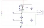
Circuit:
The idea is set Pin C.1 to be the inverse of that detected at C.2 - thus alternately charging and discharging the 100uF capacitor via the 10K resistor. When I look at the signals on C.1 and C.2, this is what I see:-
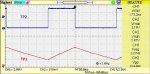
Using a 5.1V supply, the upper and lower trigger points are 2.1V & 1.87V respectively (0.41 * Vsupply & 0.37 * Vsupply). Not only do these not match the published figures they are suspiciously close together.
I tried two methods of detecting the state of Pin C.2. One was to steal some code that Hippy posted recently using the 'edge detection' logic. The other was a much more straight-forward "if PinC.2 = 1 " then "low C.1" type approach:-
What is going on?
The documentation states that a "high" will be any voltage > 0.8 * Vsupply and a "low" any voltage < 0.2 * Vsupply. For some reason, I measured rather different values in my test circuit, but I have no idea why!
Circuit:
The idea is set Pin C.1 to be the inverse of that detected at C.2 - thus alternately charging and discharging the 100uF capacitor via the 10K resistor. When I look at the signals on C.1 and C.2, this is what I see:-
Using a 5.1V supply, the upper and lower trigger points are 2.1V & 1.87V respectively (0.41 * Vsupply & 0.37 * Vsupply). Not only do these not match the published figures they are suspiciously close together.
I tried two methods of detecting the state of Pin C.2. One was to steal some code that Hippy posted recently using the 'edge detection' logic. The other was a much more straight-forward "if PinC.2 = 1 " then "low C.1" type approach:-
Rich (BB code):
#picaxe 08m2
#terminal 38400
#no_data
#no_end
;
; SFRs
;
; Datasheet values to Pe6 conversion
;
; eg 099h => 039h
;
;  0    9    9
;0000 1001 1001
; |   |xx|   /
;  \  / /   /
; 0011 1001/
;   3    9
;
;Symbol OSCON = $39     ;$099 - Oscillator control

;Interrupt On Change SFRs

Symbol IOCAP = $F1      ;$391 - Capture positive edges
Symbol IOCAN = $F2      ;$392 - Capture negative edges
Symbol IOCAF = $F3      ;$393 - Capture flag


setfreq M32

Version #1

      PokeSfr IOCAN,%00000100       ;capture negative-going transitions on C.2
      PokeSfr IOCAP,%00000100       ;capture positive-going transitions on C.2
      PokeSfr IOCAF,0               ;say none captured so far

      high C.1                      ;start capacitor charging
do
      PeekSfr IOCAF, b0             ;get no. of edge detections

      if b0 <> 0 then               ;got an edge
            toggle C.1              ;reverse charge/discharge
            pokeSfr IOCAF,0         ;clear edge detection.
      endif
loop

Version #2

do
      if PinC.2 = 1 then            ;when pin is "high",
            low C.1                 ;discharge capacitor
      else                          ;when "low"
            high C.1                ;charge it
      endif
loop
Last edited:
") . I wonder why Microchip felt the need to add the dotted-lines to the graphs (which must equate to operation at Absolute-zero or 500°c!). I understand that logic levels have a range of values, but I naively thought that the point of adding a Schmitt trigger was to put them within a more clearly defined range.
. I wonder why Microchip felt the need to add the dotted-lines to the graphs (which must equate to operation at Absolute-zero or 500°c!). I understand that logic levels have a range of values, but I naively thought that the point of adding a Schmitt trigger was to put them within a more clearly defined range.