sample rate
- Thread starter eitan
- Start date
Sampling at 15 / sec (worst case in your specification) requires a budget of 66mS / sample.
Allow some time for pre-processing in your code of the same, lets say 5mS
Allow some time to get the sample out on the serial port at 9600baud say 10mS per sample (1/9600 * 10 bits x 10 characters e.g. SEROUT ("V = 3.10 v")
Allow some time to go back around the loop to start the process again and do some simple tests, like are all samples complete, has the routine finished, lets say 5mS for that
Leaving a total budget of 66 - 5 - 10 - 5 = 45 mS for your ADC to do the conversion. Someone on this forum, I can't find it just now, has determined the conversion time for an 8 or 10 bit conversion, which in this example needs be as fast, if not faster than 45mS.
All this leads to a formula that you can re-arrange to give you baud rate and determine the maximum speed, or conversely fine tune all of the numbers to optimise your result for sampling speed as required. If you produced a simple draft sampling programme you can use the timing table values for each command in this forum to determine your maxmium speed. It looks like ADC conversion time is the determinant.
Last edited:
mrburnette
Senior Member
The DC input impedance is in megohms. The circuit output impedance driving the ADC should be no greater than 100K but most will recommend less-than 50K. This is due to the capacitance on the AD that must charge & discharge... so there is an AC impedance concern.hello
I need to sample my sensor 10-15 times in a second (sample and send via SEROUT(baud rate is TBD)).
IS 18M2 or 08M2 running 4MHz can do that? - how to calc how many sample per sec I can get?\
another thing, what is the ADC input impedance for 08M2 or 18M2?
BR
Eitan
EDIT: THE CORRECT PICAXE maximum serial resistor value is 10K... my error being caught by watchful members' eyes. As eluded to in other posts, this is a rule-of-thumb value provided by Microchip in their datasheet; example PIC41440B (14M2). There are lots of assumptions and gotchas that go into this number... one should be aware that other chips and especially proprietary AD chips may make other suggestions.
With most things, one should consult the manufacturer's sensor data sheet to determine max sensor cycle time. For the PICAXE portion, I would recommend trial-n-error, the old experimental way of do doing thing. The reason I recommend a prototype is PICAXE timing is difficult to time-box because YOUR code will dictate the loop timing. I have had situations where just adding one variable had "broken" code. There are resources here to help you estimate, but only your actual code will qualify work vs failure.
") Ray
Ray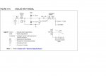
Last edited:
BeanieBots
Moderator
Absolutely, anything greater than 10k can lead to inaccuracies.For full adc accuracy 10K source impedance is recomended...
Most commands at standard clock rate take ~250uS to execute and that includes ReadADC/ReadADC10.
The longest single execution by far will be the serial out quite simply because it takes a long time to send serial data no matter how fast everything else runs.
The question was "another thing, what is the ADC input impedance for 08M2 or 18M2?" Therefore the reference to maximum series resistance could be misleading. Assuming that the read error is less than the least significant bit, for a 10-bit conversion from a 10K source, then the ADC input impedance must be at least 10,000K.
If you do this:
PRINT time
FOR i = 1 t0 10000
;do nothing
NEXT i
PRINT time
PRINT time
FOR i = 1 t0 10000
READAC variable
NEXT i
PRINT time
Then (second time duration - first time duration) / 10000 is good enough for how long does READADC take, do the same for READADC10 etc.
PRINT time
FOR i = 1 t0 10000
;do nothing
NEXT i
PRINT time
PRINT time
FOR i = 1 t0 10000
READAC variable
NEXT i
PRINT time
Then (second time duration - first time duration) / 10000 is good enough for how long does READADC take, do the same for READADC10 etc.
westaust55
Moderator
Some indicative timing for various PICAXE Programming commands covering various PICAXE chips is provided in the information attached to this thread:
http://www.picaxeforum.co.uk/showthread.php?17782-PICAXE-program-Size-Optimisations-and-Speed
http://www.picaxeforum.co.uk/showthread.php?17782-PICAXE-program-Size-Optimisations-and-Speed
The source impedance is more to do with the acquisition and wozzit time for the ADC module in the PIC.
With direct PIC programming all the parameters can be adjusted, some even suggesting <2K source impedance depending on the other settings.
Check the PIC Data Sheet.
I don't think much of this is available through the PE.
As there is a tiddly switched capacitor involved the effective input impedance is difficult to nail so isn't necessarily as suggested by MFB.
It would be better to know what the sensor (output or input which-ever way you look at it) impendance is. For exmple in the unlikely case of a very high sensor impedance then the PICAXE impedance would be an important consideration for accurate readings, but in the converse case and assuming the output impedance is less or much less than the PIC, then it really does not matter that much.
Read the sensor with say a DVM and then read it with your PIC and compare the results.
Read the sensor with say a DVM and then read it with your PIC and compare the results.
It's not as simple as that MFB. You're thinking 'DC'.
Your ADC closes a little switch to charge the cap, then opens the switch and performs the conversion.
The source impedance must be low enough for that cap to charge during the acquisition time (+leakage).
As you know, current is coulombs/time so the more the number of samples per second then the greater the charge flow.
For a single sample the impedance (in conjunction with the leakage) would appear to change with time.
So, it is tricky to nail an input impedance.
The recommended source impedance varies a bit with the chosen PIC, so have a read (and have a play).
And have a look at the ADC section of PIC data sheets. I'd spend more time thinking about the recommended source impedance rather than the theoretical input impedance.
BeanieBots
Moderator
In addition to Dippy's excellent description, it also depends on what the cap has been used for before. I.e. if the ADC was being used on a different pin with a different voltage just before hand. The effects of the sample & hold cap can be minimised by fitting a much larger cap (~100nF) directly on the ADC input pin but that will effect response time.
BeanieBots
Moderator
If it takes a fortnight to charge a farad, then a tiddly will only take a jiffy..... how many tiddlys in a farad? ...
@eitan:
If your sensor really is ~10M, then you WILL need an op-amp buffer or similar.
Hi,if I use faster clk, will the ADC convert time will be fater too or it is not depend on clk ?
The PIC A/D conversion only takes about 10us but the PICAXE instructon takes about 800us to execute. There presumably also will be many other instructions in your code with similar execution times, but you can indeed increase the clock speed to reduce them all (except for the serial comms of course).
But, if your sensor really does have a 10Mohm source impedance then the design of your voltage follower/buffer might be the limiting factor. However, the input "impedance" of the PIC is not really relevant (or even definable) as it's primarily a leakage current, largely independent of pin voltage, so Ohm's Law doesn't apply (meaningfully).
Cheers, Alan.
Perhaps let people know exactly what this sensor is and point us to its datasheet if you have one. That will allow members to assess if it has been interpreted right and what the best solution for it is.my sensor is some kind of 10Mohm resistor
Possibly ... but "some kind of 10Mohm resistor" is not very specific. Certainly you can provide a better description than that...my sensor is some kind of 10Mohm resistor so I think I must use voltage follower/buffer using OP amp.
Perhaps a part number or datasheet or a link to where you purchased it.
The conversion will be faster but conversion speed related to Picaxe ADC10 is will not be an issue. 15 times per second is no problem at all. Each conversion at 4MHz will take approximately 1.2ms. I would be more concerned with how to interface the "sensor" to the Picaxe....about how many samples per sec - if I use faster clk, will the ADC convert time will be fater too or it is not depend on clk ?
Eitan
What's that?no, it is moister sensor (-: