RS232 to TTL Converter

johndo

Member
Hi Everyone

I was wondering if you could help me with a query regarding connection to the picaxe.

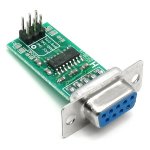
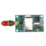
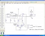
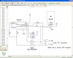
I am currently working on a wireless garage alarm which will alert me of an intruder back at the house. This involves a 433mhz transceiver module which can have parameters programmed into it through a RS232 to TTL converter module and also an 18X picaxe

The tranceiver module was purchased with TTL interface to work well with picaxe. This works great, so wanting to have access to to the tranceiver at any time I have installed the TTL converter module in the enclosure that houses the project, which then plugs into the serial port on the computer.

My question is, can I have access to the picaxe later on, ie - download through the RS232 to TTL converter instead of having to add another port for the traditional download cable/circuit? The cnverter module has TX & RX outputs on it, can i hook these up to the serial in/serial out connections that are usually used in the download circuit.

Many thanks...I hope i have explained myself enough

Kurt...
 

Dippy

Moderator
Well, a drawing would have saved potential confusion.

In answer to the question as I see it ... well, check out the PICAXE download circuit that allows safe serial from an RS232 level....

There are simple ways if you wish to buffer/invert a genuine RS232 signal too if going into a standard USART. Just a couple of resistors and transistors.
 

johndo

Member
Thanks for the fast replies... I have the converter module mounted as a plug on the project box. The main question is can i use the converter to download to picaxe?

A picture of the converter is attached below...

This is the 433Mhz module i'm using...

http://www.jizhuo.com/page/en/product_detail.asp?PID=126

Basically can i download to picaxe in TTL format???

Sorry if i dont know what i'm talking about :)
 

Attachments

Last edited:

Dippy

Moderator
Oh I see. Download code to a PICAXE via a standard RF link?
Well, I haven't seen it done yet. I'm not saying it's impossible as people have done similar things with bootloaded PICs.

I remember I chatted with hippy about this several years ago (for the older AXEs) and we concluded that a bit more gubbins was required. If given the comms details then it would be possible.
It's too long-winded to try and explain here, so I'll leave that to hippy as he likes typing.

I'm sure if the demand (i.e. more than a handful of people) was there that Rev-Ed could produce something in a short period ... but would people pay a tenner?
 

hippy

Technical Support
Staff member
Yes, you can download to the PICAXE using TTL voltage signals. As long as there's a mechanism to switch the serial interface between 'reporting' and 'programming' and as long as the signal polarities are correct it should work.

Whether this can be achieved with what you have is a different matter, mainly coming down to signal polarity. If your serial converter contains a MAX232 or similar, it will be inverting the signals from/to the PC and these will be incompatible for direct connection to the PICAXE download circuit. That can be resolved by using additional inversion.

Added : Related to Dippy's reply, can you clarify if you mean downloading via a wired PC connection through the converter or over the wireless link ?

I would say wireless downloading is possible but incredibly difficult and complex to achieve which effectively boils down to "not feasible".
 
Last edited:

Dippy

Moderator
Oh, sounds like I got I wrong... again.

Please post an image of your proposed SCHEMATIC - it could save the rest of us a lot of typing and head scratching :)
 

johndo

Member
Thanks Dippy & Hippy...

Yes it is for download via wired connection... Just thinking of neatness of the project and convenience to have all comms go through the one plug.

Hippy thanks for the tip about inversion, will look into that seeing that the RS232 to TTL converter module does use a MAX232 chip in it.

I actually did try using the converter to download to picaxe this afternoon and it didnt work!
Would you need some extra resistors in the circuit as a buffer or just hook it up at the junction of the 10k and 22k and serial out?

Would the RF Module also using the converter be automatically inverting it, as it has TTL interface?


Just to clarify things -

Computer > 9 pin D9 serial cable > RS232 in > Converter > TTL out > Picaxe & RF Module via selectable switch...

Kurt...


Stan...

What do you think of the RF module...Lets just say not cheap, but needed the extra power... BTW - power is adjustable via software...
 
Last edited:

manuka

Senior Member
JohnDo: Your module is one I've not wrestled with, but it looks akin to swag of similar ( especially HAC) arising from Shenzhen (the Chinese factory megacity just "over the road" from Hong Kong). The Chinese are very big on remote meter reading,and there must be a market for 100s of millions of such 433 MHz Tx/Rx.

I'm not going to tackle setup etc at this local late hour,so suggest you PLEASE check my HopeRF resources , where much of this has been outlined already.

That receiver sensitivity figure looks wonderful & reminds me of the Yishi versions Dr_A swears by ! N.B. It'd help us as all if you also indicate just where you are,as this aids pointing to local parts supplies etc.
 
Last edited:

hippy

Technical Support
Staff member
For a wired connection it seems that the converter would have its RX/TX either switched to the RF module, or to some 'logic inverter' which in turn connects to the PICAXE download circuit.

There are a number of ways to do this from using a simple DPDT switch to digital switching. It's all possible, just a question of designing an appropriate circuit.
 

johndo

Member
Hippy,

Yes, a DPDT switch would be perfect!

Is this what you mean by a logic inverter?

http://www.picaxe.orconhosting.net.nz/hopettlsch.jpg

It takes the TTL from the MAX232 chip which has been inverted and restores it back to it's original RS232 "inversion" but with TTL voltage levels? Im starting to understand it! I think?

Anyway thanks alot for all your help! Hopefully will put it in the finished projects section one of these days!

Cheers, Kurt...
 

johndo

Member
Manuka,

With the RF modules , I ordered them online and received them within 7 days from china...Not bad!

I can give you a link where to buy if you like... PM me.
 

hippy

Technical Support
Staff member
Is this what you mean by a logic inverter?

That may be one solution but there are many possibilities. It's hard to advise on specifics without a full circuit diagram, data sheets or information on signal voltages and so on. There may often be no agreement on a single best solution.

I'd personally consider going for full digital switching if I wasn't seeking an easy option and would consider a mechanism of having the switching in the remote assembly but controlled through the cable to the PC, maybe automatically if possible so the remote unit knows if being programmed or simply monitored / not connected. So much though depends on what you want, how much you're prepared to spend, and how much time you're willing to invest.
 

moxhamj

New Member
Logic inverter = a couple of gates from a 74HC04

I built a circuit some years ago to do this so I had only logic levels on my breadboard. (Twice a -12V line zapped a picaxe). Not an issue though for wired connections with plugs (unless you really screw up the wiring)

RS232 "101"

Resting = -9 to -12V. Active = +9V to +12V.
Max 232 chips invert. Resting = 5V. Active = 0V
Male D9 outputs on pin 3. Female D9 outputs on pin 2. Pin 5 is ground.

Ok, the picaxe "download" circuit has two resistors. It depends on some internal circuitry on the pic chip, but essentially the -9V gets turned into 0V (resting) and the +9V gets turned into 5V (active).

The max232 inverted the signal, so you just need to invert it back again.

From the pic to the PC, resting is 0V which the PC interprets as -12V, which technically shouldn't happen as signals between -3V and +3V are not valid RS232 signals, but pretty much all RS232 receivers let you get away with that.

So for the pic back to the PC, you could just wire it straight through as per the standard programming circuit.

The problem is when you start mixing real and fake RS232 signals in a circuit with switches. The nice thing about RS232 signals is you can short them, feed outputs to other outputs, shove pretty much any positive or negative signal onto any pin and nothing bad will happen.

If you have switches, there might be a small chance you wire it up wrong and feed -12V into the picaxe output pin 0. And that wil zap the picaxe.

I've gone for plugs and sockets rather than switches. But you could always build a little board with one D9 female and two D9 males and a double pole double throw switch and call that a RS232 switcher board.

I can think of many different ways to do this. One question - does it have to be a switch or are plugs ok?

One thing worth considering - if you use that RS232 board on the left, that outputs TTL, then you use two gates from a HC04 in and out of the max232 so now you have signal levels that can program a picaxe. One to physical pin 2 and one to physical pin 7. BUT - when you remove the programmer, pin 2 will be floating. So will need a 10k pulldown resistor. And if you are putting one resistor in, may as well put the other 22k in and put a D9 female on the picaxe for programming.

Then another D9 that goes to the radio module and use Input 3 and output 1.
 

johndo

Member
G'day Dr_Acula,

Thank you for that informative piece on RS232...

Just to make sure that i understand -

Resting = -9 to -12V. Active = +9V to +12V.
Max 232 chips invert. Resting = 5V. Active = 0V

so we need to invert the signal back to

Resting = 0V. Active = 5V

On the picaxe side of things, it is far neater if i only had one plug on the project box = D9 male. Could i leave the 10k & 22k in situ on the picaxe board so when i switch the DPDT at the output of the converter the picaxe is not left floating? Or does the output of the converter have to be connected directly to the pins of picaxe?

Cheers.
 

moxhamj

New Member
Yes, that sounds right.

Ok, one plug. Yes, you can leave the resistors in situ and indeed, I think this is considered standard practice (not a huge expense!).

So, will you be needing inverters? There are so many options here. Can you draw up what you are planning to do now?
 

johndo

Member
Dr_Acula

Drawing! LOL Not one of my strongest points :) Not sure how to...

Would manuka's circuit be ok. http://www.picaxe.orconhosting.net.nz/hopettlsch.jpg
Just put the resistor on the emitter side of the tranny and connect picaxe to this junction and collector side of tranny to 5v? I need to have logic 0=0v and logic 1=5v or close to it.


The use of a DPDT switch seems the most simple way to move between progamming the picaxe and RF module with low complexity. Just flick the switch to one position to programme the RF module then flick to the other position to do same to the picaxe.

This project is very early days, so expect some updates to follow in the next couple of weeks.

Just on a side note this project will need an LCD interface, has anybody used P.Andersons displays? Looking at the 4 line Yellow on black with serial interface...Looks very nice!

Thanks for your help mate!
 

Dippy

Moderator
Johndo,
sounds like it's coming along nicely. Good stuff. (as the actress said to the bishop).

"Drawing! LOL Not one of my strongest points :) Not sure how to..."

- On a slightly serious note and meant in the nicest possible way...

Please remember that people are giving you free tuition/advice.
It REALLY does help and is appreciated that questioners supply correct and clear info.
A drawing may take you 20 minutes, but it may save a total of hours for the people helping you free of charge and in their own time. Help on this Forum is purely voluntary.
I have seen dozens of examples of ambiguities causing pages of wasted thread all for nothing in the past.
Wasted time really pees people off.
So please help others to help you - and this applies to everyone including me.
 

lbenson

Senior Member
For drawing schematics, expressPCB offers a free schematic program which I find easy to use. Others on this forum like Diptrace--also free and intuitive. Learning one of these will save lots of time in the future--your own as well as that of those who might be willing to help you.
 

manuka

Senior Member
Johndo: Even near trivial PC drawing/photo editing programs (Windows Paint ?) suit simple circuit diagrams!

Such tedious issues as intuitive interfaces,learning time,costs & hardware needs often far outway the features of more professional packages (Photo Shop etc). Hence 13 yo. "fits on a floppy" MGI PhotoSuite,a W95 era offering that came with my first digital camera in 1997,still allows even the meanest netbook/thin client/old laptop to rustle up slick draft schematics. NB-(if Googling) Roxio took over MGI late 2001. Stan.
 

Attachments

Last edited:

johndo

Member
I will post a schematic next time! Anyway, thanks for all of your input and advice. I think the problem has been solved, and Hippy, your GREAT at what you do, you had it sorted by post #6. Look foward to posting updates shortly...

Cheers...
 

moxhamj

New Member
Good to hear it is sorted! Am looking forward to updates.

Re drawings I've tried a few methods:
1) Draw it on a piece of paper with a thick pen/marker, and take a photo. This is probably the quickest method. Old school and it works.
2) Draw in a myriad of programs and capture it somehow as a jpeg. Most drawing programs can save a jpeg. But if not, I have my old shareware version of paint shop pro from decades ago that can set up as a screen capture and then capture when you hit F11. Then grab the bit of the screen of interest, save as a new file. I would do this 4-5x a week.
3) Learn a program like Eagle and install a "print to pdf" program. Print the program and save as a pdf and upload.
4) Going back a few years, the forum couldn't handle any sort of attachments, and there were some amazing examples of Ascii Art. I think there is even a schematic drawing program that works in ascii art. Others are expert on this and may post more, but I used it a few times and it was pretty easy.

Option 1 is probably the easiest. If you want to be super neat, use graph paper.

BTW, what was the brand of radio module you are using?
 

johndo

Member
Dr_Acula

Ha! I like option #1. Sometimes back to basics is the best! My Dad always said K.I.S.S...

The model number of the module is JZ-871. The reason i chose this one over the hope modules is the extra power available - 100mw vs 10mw with hope and also the ease of communication between the modules. And the modules block out any other rubbish and just
talk to each other. Here is the link to the modules page.

http://www.jizhuo.com/page/en/product_detail.asp?PID=126

and where i bought them from

http://en.stkshop.com/Components/Wireless-module/JZ871-Data-RF-Module.html

It seemed to work out cheaper from this place because the manufacturer insisted on using DHL wich was very expensive. I used EMS which was about $20 AUD and got them in about 7 days.


We live on the top floor in a block of units, so the signal has to get through 3 slabs of concrete and be ultra reliable. And the quoted sensitivity is outstanding -121db at 433mhz...

Thanks for YOUR help mate!, it really helped me understand how RS232 works... What about the idea of using manuka's circuit with mod's which I mentioned in a previous post?


Cheers...
 

johndo

Member
Here's one for all you schematic freaks out there! :)

Is this something that you think would work to invert TTL levels? It's basically an adaptation of Maunka's circuit but with modification to invert TTL back to RS232 protocol...

Resting = -9 to -12V. Active = +9V to +12V.
Max 232 chips invert. Resting = 5V. Active = 0V

so we need to invert the signal back to

Resting = 0V. Active = 5V


Enjoy!
 

Attachments

Dippy

Moderator
You're new to MOSFETs aren't you. I suspect that will behave strangely and will be VERY device and R11-value-dependent. Sadly it's not a good general design.
Try it with a handful of MOSFETs. Dig out your 'scope and run up the baud rate and watch.
 

moxhamj

New Member
Cheap and cheerful TTL inverter http://www.play-hookey.com/digital/experiments/rtl_inverter.html

One transistor (eg BC547, 548, 549, 2N2222 etc) and two resistors. Total cost lesst than 10c.

(I'd probably use a 10k instead of 15k as I've got lots of 10k resistors lying around.)

Thanks for the link re the modules. Checking it out now...

Yes, nice find. I've been using

http://www.yishi.net.cn/rf/ProductShow.asp?ID=99 10mw

and

http://www.yishi.net.cn/rf/ProductShow.asp?ID=98 500mW

Very similar receiving sensitivity, price and specs.

Yours is 100mW which fits nicely between the two. I have found 500mW is a bit nasty to nearby electronic equipment, eg VGA monitors. Good to get the antenna up on the roof with those sorts of powers.

100mW might be a good compromise.
 
Last edited:

Andrew Cowan

Senior Member
Dr Ac - When I make a TTL invertor, I use that circuit. However, for going into a PICAXE, I'd use a 1K on the base and a 10K pullup (with a BC639). For minimal current draw the values don't really matter.

A
 

hippy

Technical Support
Staff member
My 'cheap RS232 inverter' has been a 74HC00 using a two resistor serial interface as per the PICAXE download circuit. I've used the same two resistor trick with a number of other microcontrollers; the current limiting resistor ( 22K for PICAXE ) has sometimes been as high as 560K ( +/-20uA injection current ) and that seems to have worked.

In this case though we are talking about inverting a TTL signal ( after conversion from RS232 ) feeding a TTL compatible input so it should be no more complicated than using any inverting logic gate. As long as there's a single power rail for everything there shouldn't be any problems. A single transistor inverter could replace the logic gate and may be easier to use if there's not a single power rail.

Of course it is possible to go beyond the simplistic and replace the RS232 converter to give switched inverted and non-inverted outputs, and many ways to do that ( including adding remote, PC-end of cable switching between monitoring and programming ). Unless brain-storming possibilities, clarity of what is exactly required to be implemented would help.
 

johndo

Member
Hey Guy's,

Finally got around to drawing up a schematic/block diagram of what I am planning to do next. Can you see any potential problems with this setup? The only problem that i can see is that the RF module and the picaxe are sharing a connection, may be a problem when you want to program the RF module?

Thanks again for all your help...

Kurt.
 

Attachments

BeanieBots

Moderator
Be aware that your signals will be inverted.
Also, why the 10k/22k arrangement on serin?
You will some odd potential divider action between the 10k pull down and the pullup resistor on the FET.
The FET is pulled up to Vcc so there is no need for the 10k pulldown or 22k current limit. However, it does mean that your incomming signal MUST idle high or the PICAXE won't work.
 

johndo

Member
That's a good point! In the traditional picaxe download circuit you MUST include the 10k pulldown resistor on SERIAL IN or the picaxe wont work. Could it be tied to V+ instead?
 

johndo

Member
SUCCESS!!! Finally have been able to download tp picaxe through the TTL converter. It was a matter of just inverting the signals. Didn't have much luck with the discrete component setup, but then tried a 4049 Hex inverter chip and worked like a charm! Thanks all for your long suffering and great suggestions.

I have updated the schematic for any one else having the same problem...

Kindest Regards
Kurt

PS: Thanks John, already on the PCB :)
 

Attachments

BeanieBots

Moderator
No need for the 22k/10k arrangement (though it won't hurt). Wire direct to the inverter output, it's 5v logic!
Why two chips (U2 & U3) for the inverters? There are SIX in just one package!
Also, as mentioned by john hauton, some decoupling would be a very good idea.
 

hippy

Technical Support
Staff member
I suspect the 10K pull-down on serial in and the 10K pull-up on the FET may have been part of the problem with the discrete version; the signal would be 0V/2V5 rather than 0V/5V.

I agree with BeanieBots, you can remove both 22K and 10K. No harm done if left in place though.

I would definitely add a 10K pull up to +V for leg 3 of U2.1. This will stop the input from ever going low when the switch is turned to the RF module. Otherwise U2.1 sees a low, puts out a high, and PICAXE operations will be disrupted, stopping, then resetting.

I'm not convinced we are there yet with the RF module connections and mixing PICAXE->RF and PC->RF. That may be best done using diode-mixing ( pointy-ends away from the RF module ) and a pull-up on RF input.
 

moxhamj

New Member
Re post #34, if the switch is in the up position then the Tx line input will be floating. That could randomly reprogram the picaxe. I think you want it to be pulled high with a 10k on the input to that inverter gate. Then the output is always low when not selected with the switch (and if connected, whatever signal there is will override the 10k pullup). Then you don't need the 10k/22k. Saves a resistor.

Re R??, would they be 1k or something?
 
Top