I would like to make a rs232 detector so that when I plug it in to an rs232 port or cable etc. If there is ANY rs232 signal present it would make an led light.If not no light would light . It would just be a quick down and dirty check to see if Im sending/receiving anything. Im not sure if such a thing is possible or not. I kn[ow with all of the protocalls etc it may not be possible. I was wondering if maybe some way readadc would work? Any thoughts? thanks
RS232/485 detector?
- Thread starter tmack
- Start date
Would something like this help?
http://www.phanderson.com/picaxe/logic.html
Also, there are several references to Logic Probe on the Forum.
Or have I misread the question?
e
http://www.phanderson.com/picaxe/logic.html
Also, there are several references to Logic Probe on the Forum.
Or have I misread the question?
e
I've put them on all my boards as part of the design. It helps a lot to trace signals through a maze of boards.
RS232 is very simple. -9 to 12V resting, and +9 to +12V when sending. So you can do this with two leds and two resistors. You don't want to overload the RS232 (it might only be a Max232 sending), so use bigger resistors and high efficiency leds. Eg 4k7. So for -9V, use 0V=>4k7 resistor=> led anode=> led cathode=>-9V. Make that a green led. Then The same line for +9V => 4k7=> led anode=> led cathode=>0V.
So essentially you have one led that lights if the volts are positive and the other lights if they are negative. You could replace the two leds with a dual led that lights different colours when the current goes in different directions.
Build this circuit for pin 3 on the D9 (transmit from the PC).
Then repeat for pin 2 of the D9.
I can draw this up if the explanation doesn't make sense")
If you want to go further and detect valid RS232 signals, that can be done with a Max232 chip and a picaxe chip. But it would only work for the baud rates that picaxe can detect.
RS232 is very simple. -9 to 12V resting, and +9 to +12V when sending. So you can do this with two leds and two resistors. You don't want to overload the RS232 (it might only be a Max232 sending), so use bigger resistors and high efficiency leds. Eg 4k7. So for -9V, use 0V=>4k7 resistor=> led anode=> led cathode=>-9V. Make that a green led. Then The same line for +9V => 4k7=> led anode=> led cathode=>0V.
So essentially you have one led that lights if the volts are positive and the other lights if they are negative. You could replace the two leds with a dual led that lights different colours when the current goes in different directions.
Build this circuit for pin 3 on the D9 (transmit from the PC).
Then repeat for pin 2 of the D9.
I can draw this up if the explanation doesn't make sense
If you want to go further and detect valid RS232 signals, that can be done with a Max232 chip and a picaxe chip. But it would only work for the baud rates that picaxe can detect.
Last edited:
Cetainly possible, as HeathKit sold an RS232 speed detector kit in the distant past. It lit up a line of LEDs (300 baud to 19,200 baud), with all the LEDs up to and including the detected speed lighting up.
If I knew the model number, you might be able to locate a schematic online.
There are also programs for the PC to detect RS232, such as this free one:
http://www.serial-port-monitor.com/free-serial-port-monitor-downloads.html
John
If I knew the model number, you might be able to locate a schematic online.
There are also programs for the PC to detect RS232, such as this free one:
http://www.serial-port-monitor.com/free-serial-port-monitor-downloads.html
John
LED plus R has got to be the simplest RS232 detector / indicator. I recommend they're put on all RS232 lines because you can then see at a glance what comms are happening, whether the Programming Editor is downloading into the PICAXE or not.
RS485 would be much the same but as it's a balanced line a bi-colour LED plus R across the two lines would work better than something to 0V ( what 0V !? ) - Orange showing proper bi-phase working, red or green showing single phase operation with one line held at 0V.
RS485 would be much the same but as it's a balanced line a bi-colour LED plus R across the two lines would work better than something to 0V ( what 0V !? ) - Orange showing proper bi-phase working, red or green showing single phase operation with one line held at 0V.
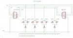
One led will stay lit when resting and then when data is being transmitted the other one will flash briefly. If it is a long string of data you will get a pretty display with both the red and green led flashing. You can even read off data to some extent - eg sending a series of hex "00"s will look different to a series of "FF"s. You can change the baud rate and get a feel for how long packets of data take to go through. The leds certainly take the mystery out of RS232.
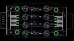
If you are really keen you could build a small board with a D9 female on one side and a D9 male on the other, and put the leds on the board. Wire pins 2 to 2, 3 to 3, 5 to 5, 7 to 7 and 8 to 8. Most RS232 doesn't use pins 7 and 8 but they are used in some cases - eg a device might put a RTS line high to ask if it can send some data and the other device puts its CTS line high to say, yes it is now ready. Downloading and communicating to picaxe only uses pins 2,3 and 5, so if that is all you are doing you could not even wire up pins 7 and 8. Maybe leave room on the board in case you do later.
See the attached drawing for a circuit idea.
Attachments
-
 47.9 KB Views: 36
 -
 87.1 KB Views: 31
Last edited: