Robot Control Circuit - Electronic Novice

rampeh

New Member
I am designing a circuit to control a tank tracked robot (one motor per track), as well as a solenoid mounted on the front of the vehicle.

I've hacked together a schematic after looking at datasheets for many an hour, and because of my limited electronics knowledge (haven't taken it at uni yet) there are a few things i don't understand. I have attatched the schematic. I am using an 18 pin PICAXE chip in conjunction with a quadruple half h driver (Probably an SN754410). The motors will run off 12V supply but i haven't bought them yet so their current draw is as of yet unknown (will be less than 1A).
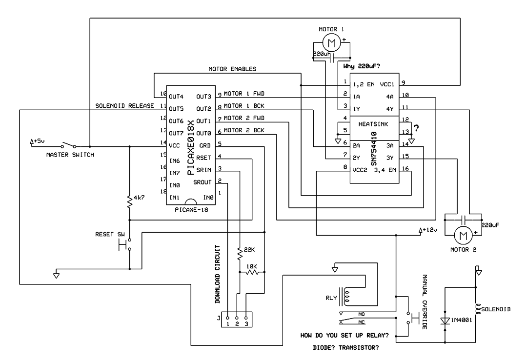


1) The Elusive Ground
From my high school electronics (i didn't pay much attention) i was lead to believe that the -ve terminal of a battery acts as ground in a circuit, but i'm not quite sure how it works if i'm using both a 5V source and a 12V source.

Can i run things from the hot of the 12V source into the ground of the 5V? Where do i ground the heatsink of the SN754410? I understand it's necessary for all parts to reach ground but i'm not sure exactly what constitutes as ground.

2) Relays
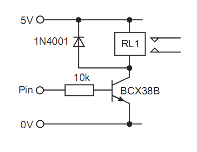
The solenoid will probably draw too many amps for the picaxe to output. This means i need a relay (and maybe a JFET to power this relay, we'll see). Anyway, the PICAXE interface guide has an example of a relay (attatched). It shows a lead from the 5V source, through the relay, to a JFET powered by the picaxe. How does that work? I'm not too familiar with transistors, but doesnt the arrow mean the emitter? Wouldnt current want to run from E to C, not the otherway round? A little help with how i would set up my relay would be well appreciated.


3) Back EMF Protection
I've read that the back EMF created when an induction powered device is turned off can blow your IC to pieces, so you stick a diode in parallel with it (Also seen in the relay example) . How does this work? Wouldn't the back EMF still want to go to ground, rather than to the 5V supply. Is it just because there's a load in front of ground that it'd rather route to 5V (no load other than the diode), my physics background would make me think the force would be stronger towards the 0V terminal.

4) Noise Suppression on Motors
How does a capacitor in parallel to a motor suppress electrical noise? Is the motors rotational magnetic field what causes the noise? What does the capacitance have to do with it (why does everyone use a 220uF capacitor?)

5) PCB Design / Crossing Traces
When it finally comes down to it, how do i make the PCB, since a lot of my wires overlap. I never see any wire bridges on small professional circuit boards (single layer), so how do they manage to get interweaving traces? Do they use tiny resistors to save time? what's the big secret, i'm having a hard time.

Final Note:
Sorry about the rant. If you see any problems with my schematic i'd love to know, Rip it to shreds i'm happy to redo it from scratch just to learn. Thanks in advance.
 

BrendanP

Senior Member
Forget about the H bridges they're a pain in the neck. Use a DPDT relay for direction control and a transistor under PWM for speed control. I guess you'll use one of these set ups for each track. H bridges are mongrel things to work with, they are more trouble than they're worth. V drop, shoot through etc.

Don't denigrate your own ability, just get in there and start hacking. (Except if it involves 240V AC or explosives then I counsel a element of caution......)
 

Dippy

Moderator
Firstly, good luck with the project. It will be an education for you.

I haven't got time to check your schematic, but I can do a couple of the questions.
Back emf.
When your transistor switches on a current flows through the relay coil poducing a magnetic field which moves the contact. When the transistor is switched off it becomes, essentially a high impedance. The current in the coil stops. The magnetic field collapses and produces a reverse voltage . Check your physics to calc things. At the relay-transistor junction a high voltage will be produced. Many times higher than the supply. The diode, essentially shorts it out, so that you don't have that dirty great spike on the collector (in your picture). This can, by the way, introduce a spike onto the power rail. I always have a capacitor at the diode/V+ point too - if you like to 'absorb' it.
Same will apply if using FET and be aware that some FETs can be very touchy about high voltages.

PCB Design.
You've obviously had a little dabble to realise that links are required when drawing out the pcb tracks. Well, those links can be done in copper when the pcb has copper top and bottom. So, you can then join tracks on the underside with tracks on the topside. Then you can join the 2 layers (top & bottom) with holes that are plated internally to conduct top to bottom. Check out some pro boards and have a look for little holes apparently on their own.
These little holes are called vias. They are plated internally.
Double-sided boards are also referred to as PTH - Plated Through Hole.
Home-made double-sided boards usually have a bit wire soldered through the via to join top & bottom.

Solenoids.
You may not need a relay for it. A FAT MOSFET will do it most likely - with a diode. You select a MOSFET by the worst case coil specs. e.g. how much current it will pass when ON, how long will it stay ON, things like that.

Grounds.
Yes, the negative marked battery terminal is USUALLY the Ground. If you are using 5V and 12V battery sources you 'common' the ground so that all voltages are relative to the Ground reference. DO NOT allow 12V to get to PICAXE.

Phew, enough... and I haven't even mentioned reading Data Sheets.
 

Rickharris

Senior Member
Personally I have used H bridges with great success especially for low current applications like small robots. But there you go we all have our approaches. A relay works as well.

Why not as Dippy says drive the solenoid from a MOSFET and save on the relay. - The MOSFET acts as a switch.

Connect all the negatives together that way everything is correctly referanced to the other voltages. Including the heatsink although this is not necessary it can float as this makes no difference to its heat sinking capability.

The diagram looks OK apart from the lack of diode across the relay coil (Flywheel diode if you want to look it up.)

To sudden changes in voltage, like a noise spike the capacitor acts like a short circuit so it shorts out noise before it gets into the system. 220Pf is just an average value most small capacitors would also work to some degree.

To avoid frustration (OK to minimise) try to get one bit working at a time, drive mechanics (drive motors direct from a battery to test, Drive control system, Weapons or what ever.
 

gbrusseau

Senior Member
I have used the SN754410 with great success. The idea of using 4 or even 8 transistors and several resistors to build an H-Bridge from discrete components and wiring them to a PCB seems very troublesome to me. The PCB wiring would be a headache and the footprint of the PCB would be troublesome as well for me. I vote for the SN754410.

Pins 4,5,12,13 are the common ground connections to the SN754410 IC
for both the +5 volts and the +12 volts. These ground pins also serve as a heat sink, bonded directly to the dice. Solder them all together and to your ground plain makes a good heat sink.

The SN754410 is stackable, one on top of the other, to give you a 2, 3, 4 , etc amp H-Bridge. See attachment.

Good Luck
 

Attachments

Last edited:

rampeh

New Member
Solenoids.
You may not need a relay for it. A FAT MOSFET will do it most likely - with a diode. You select a MOSFET by the worst case coil specs. e.g. how much current it will pass when ON, how long will it stay ON, things like that.
The thing is, i don't know anything about solenoids. I have had this problem with selectring a solenoid to use. The shear force it has to hold is around 100-200g, but all the specs about solenoids depend on duty cycle, which confuses me. The solenoid i wish to know pretty much just needs to turn on for <1 second, then turn off (for at least a minute). Is this a 1/60 duty cycle? How do i calculate everything.

I was also wondering the highest current draw the picaxe can safely handle, and how circuit resistance is determined when dealing with the picaxe. Do you assume all pins loads are in parallel?
 

Dippy

Moderator
Firstly, the force varies with the position of and how far the plonker has to move.

Secondy, the duty cycle: yes, you would have a 1 in 60 duty cycle. It's mainly about heat.
I just looked at a couple PED data sheets. Not too helpful.

There are people here with a lot of solenoid experience so wait...

"I was also wondering the highest current draw the picaxe can safely handle."
Do you mean how much current a pin can sink/source? (for switching loads?)

I would recommend you get the PIC data sheet from Microchip, but I don't think you're ready for 600 pages.
Bottom line:
Each individual pin an sink/source 25mA
BUT,
if using several pins on a PORT then the total must NOT exceed 200mA. There are up to 8 pins on a PORT, you can do the maths.

However, I would recommnd you get a copy of a PIC data sheet and look at the 'ELECTRICAL SPECIFICATIONS' - in fact, I recommend that EVERY Picaxer gets a copy :) as this question pops up so regularly.
 

hax

New Member
I had a good look over your circuit. Answers to your questions in your order:

1. Grounding all sources means that all the "-" wires have to be connected together from your battery packs. It's as simple as that. All sources must have the same common ground.

2. Setting up the transistor to run the relay is shown correctly in your picture copied from the rev-ed manual.

3. Back EMF is called "BACK" EMF because it flows the wrong way. When a coil gets de-energised, a high voltage gets generated on the "-" side of the coil. This current takes the path of least resistance through the diode and shorts out. If the diode is not there..... it takes the path of least resistance through your transistor (blowing it up in the process).

4. See comments below.

5. No secret really. I generally look at the diagram and orient as many inputs of one IC to as many outputs of another IC. Practice makes perfect. Or use an autorouter in your PCB design package. Some are good, some not so good.


Comments on your diagram:

Don't wire the relay directly to the picaxe pin. Use the transistor cct.

1. The capacitors on your motors should be 120 pico farads, not 120 micro farads as your diagram shows.

2. I looked up the datasheet for the SN754410 I could not find it but I found this

http://design.stanford.edu/Courses/me118/pictures/Win02Projects/BirthOfByter/pdf/SN754410_Module.pdf


One diagram has the wrong pinouts for the SN754410. I'm guessing its yours? Not sure.

Namely, you have labelled VCC1 as pin 9, but my document shows VCC1 as being pin 16

you have shown motors connected to pins 3 and 7, and 11 and 15 but my diagram shows 3,6 and 11,14.

That then puts out the enable pins,.... etc. Maybe the diagram I am looking at is incorrect, I dont know.


In any case, see the 6 diodes in the document I am looking at, that looks like a good way to cut down noise from the motors.

And thanks for writing a detailed question. :)

Its always easier to answer.
 

rampeh

New Member
Thanks for the help guys. And yeah, the SN754410 has different pinouts, i was half asleep when i drew it up and labelled the outputs the wrong way round! I'll fix it up, thanks for noticing.

Haxby, In the pdf you linked to me, it says

J3, pin 2 : Since the SN754410 is capable of switching two H-Bridge channels at a maximum of 1A each,
care must be taken in the methods employed returning this substantial current to ground. For this reason, a
separate high-current ground connection is available at J3, pin 2. A separate connection should be made
between J3, pin 2 and the power supply of the motors/loads connected to the IC&#8217;s outputs. This will ensure
that the logic power supply maintains a clean ground.
I thought i was supposed to ground everything on the same wire, just connect all the grounds to both the negative terminal of my batteries. What is the passage telling me to do? Also, what is the purpose of the grid of diodes along the motor terminals? More Back EMF supression? I thought the SN754410 has inbuilt protection diodes, but i may be wrong.
 
Last edited:

Wrenow

Senior Member
Some general advice. Check the specs on any motors you use thoroughly and design for the stall draw. Commonly available 550 style motors are handy, with their 1/8" shaft, and cheap on the surplus market, and only draw an amp or so free-spinning or light load - but stall that sucker, and you draw up to almost 90A each!

Also, decide whether you want to spend your time designing a circuit that is already available off-the shelf, or working out the mechanical and other kinks. Tank style controllers for bots are readily available as mature products for a not unreasonable price from various sources you should be looking into for other things anyway, like Lynxmotion, RobotMarketplace, ServoCity, Pololu, DimensionEngineering, etc. You might also find Servo Magazine and Robot Magazine useful sources.

The antweight robot guys have really done the heavy lifting for those of us who need their stuff in RC Model Warship Combat.

Not going with an RC (radio controlled) robot - wanting autonomous? Easy to program the Picaxe to send the standard hobby RC servo pulses to control the other stuff.

Good luck,

Wreno
 

hax

New Member
@rampeh

That paragraph is talking about the voltage drop that may occur on some PCB tracks that are carrying high currents. At 1 amp, this is not much of a worry if you use 4mm track width.

It is common to run separate grounds between motors and logic circuits, and then at one central point in the PCB, bring them together. Preferrably at the point where the battery connectors are.
 
Top