Right sony Remote
- Thread starter zneb
- Start date
PhilHornby
Senior Member
Are we talking about this project http://www.otvinta.com/download10.html ?
This Youtube video implies that your Sony Remote is programmable ... so you definitely shouldn't need another Remote!
However, are you sure it's sending the codes that the Picaxe code expects?
It would be a good idea to post the Picaxe code you're using!
This Youtube video implies that your Sony Remote is programmable ... so you definitely shouldn't need another Remote!
However, are you sure it's sending the codes that the Picaxe code expects?
It would be a good idea to post the Picaxe code you're using!
Yes that is the project and I'm using the code they wrote below...…….
The underlying Picaxe code is as follows:
do
irin b.6, b1
if b1 = 116 then ' forward
high c.3
high c.2
low b.4
low b.5
elseif b1 = 51 then ' right
high c.3
low c.2
low b.4
high b.5
elseif b1 = 52 then ' left
low c.3
high c.2
high b.4
low b.5
elseif b1 = 101 then ' stop
low c.3
low c.2
low b.4
low b.5
elseif b1 = 117 then ' reverse
low c.3
low c.2
high b.4
high b.5
endif
loop
It downloaded fine using the cable you provided.... Thanks for coming back so Quick I'm anxious to get this working to show My grandson what He could all learn about great stuff...Gary H
procfanousek
Member
I have programmable remote Vivanco UR 82 that can send Sony codes. As far as I remember, not every Sony code worked with PICAXE. I had to find the right one.
I have programmable remote Vivanco UR 82 that can send Sony codes. As far as I remember, not every Sony code worked with PICAXE. I had to find the right one.
Thanks for the info, I tried over 28 different codes in the one I have and no responseI have programmable remote Vivanco UR 82 that can send Sony codes. As far as I remember, not every Sony code worked with PICAXE. I had to find the right one.
procfanousek
Member
Isn´t wirng wrong? As for IR sensor I use with PICAXE TSOP34836 and it is wired exactly as here:
http://www.picaxe.com/Circuit-Creator/Sensors/Infra-red-Sensor/
I noticed that there is pull-up 330R and capacitor 100n at Otvinta. Should be 4k7 and 4,7uF according to the circuit at picaxe.com
http://www.picaxe.com/Circuit-Creator/Sensors/Infra-red-Sensor/
I noticed that there is pull-up 330R and capacitor 100n at Otvinta. Should be 4k7 and 4,7uF according to the circuit at picaxe.com
I have programmable remote Vivanco UR 82 that can send Sony codes. As far as I remember, not every Sony code worked with PICAXE. I had to find the right one.
Isn´t wirng wrong? As for IR sensor I use with PICAXE TSOP34836 and it is wired exactly as here:
http://www.picaxe.com/Circuit-Creator/Sensors/Infra-red-Sensor/
I noticed that there is pull-up 330R and capacitor 100n at Otvinta. Should be 4k7 and 4,7uF according to the circuit at picaxe.com
Isn´t wirng wrong? As for IR sensor I use with PICAXE TSOP34836 and it is wired exactly as here:
http://www.picaxe.com/Circuit-Creator/Sensors/Infra-red-Sensor/
I noticed that there is pull-up 330R and capacitor 100n at Otvinta. Should be 4k7 and 4,7uF according to the circuit at picaxe.com
I notice I used a IR receiver diode TSOP38238 could that be also part of the problem. I don't know much about the numbers 4K7 and 4,7uf are they resisters ? also what does OTvinta mean .I want to use your fix but need to do it right. I'm going to add some photos also which might show where i'm wrong>Opps the files are to big I'll have to pass and take them over.Isn´t wirng wrong? As for IR sensor I use with PICAXE TSOP34836 and it is wired exactly as here:
http://www.picaxe.com/Circuit-Creator/Sensors/Infra-red-Sensor/
I noticed that there is pull-up 330R and capacitor 100n at Otvinta. Should be 4k7 and 4,7uF according to the circuit at picaxe.com
4K7 is a resister. It is a 4.7 K Ohm resister or 4700R. Same...... The 4.7uf is a capacitor - 4.7 micro-farad capacitor. Follow Prokanousek's advice above using a 4.7uf capacitor instead of the 100n, and a 4k7 resister instead of the 330R. It should then work on one of the Sony TV codes.
I notice I used a IR receiver diode TSOP38238 could that be also part of the problem. I don't know much about the numbers 4K7 and 4,7uf are they resisters ? also what does OTvinta mean .I want to use your fix but need to do it right. I'm going to add some photos also which might show where i'm wrong>Opps the files are to big I'll have to pass and take them over.
Thank You .Will Try For Sure4K7 is a resister. It is a 4.7 K Ohm resister or 4700R. Same...... The 4.7uf is a capacitor - 4.7 micro-farad capacitor. Follow Prokanousek's advice above using a 4.7uf capacitor instead of the 100n, and a 4k7 resister instead of the 330R. It should then work on one of the Sony TV codes.
PhilHornby
Senior Member
I didn't provide a cable ... I'm just a user here, like yourselfYes that is the project
It downloaded fine using the cable you provided....
") .
.The 'picture' ( I hesitate to call it a schematic!) on the Otvinta.com site, shows a Picaxe 20M, but as I understand it, you couldn't use Pin 12 on the (ancient) Picaxe 20M for IR input?
You can use Pin 12 on the current Picaxe 20M2, (where it is known as "B.6" - which matches your code). So, which Picaxe are you actually using (the 20M or the 20M2)?
If it's the 20M2, the wiring appears vaguely correct (I've used TSOPs without the resistor or capacitor, with seemingly no ill effects...they probably only start to matter in 'harsh' environments).
I would say the IR codes that are being tested for (116, 51, 52, 101 & 117) don't look very likely - I've not seen them documented anywhere. (They may well exist on some obscure Remote Control and might have been chosen because they are obsure (thus avoiding interference)).
What we could do with knowing, is what value (if any!) is present in variable "b.1", immediately after the
irin b.6, b1 statement completes (for each of your desired button presses).Do you know how to use the
debug or sertxd statements to do this ... or would you like some help with it?procfanousek
Member
I think that the wiring diagram is drawn in Fritzing. I looked into database of Fritzing 0.9.2b.32.pc and among PICAXEs there is only 20M. This is perhaps the reason why Otvinta used it. Also Picaxe Manual 2-BASIC commands does not say that irin is possible on 20M, only on 20M2. Do you have PICAXE 20M or 20M2 then?
inglewoodpete
Senior Member
I suggest that one of the two following pieces of test code be used to determine what IR codes, if any, are being received by the PICAXE.
For a 20M:
For a 20M2:
For a 20M:
Rich (BB code):
#PICAXE 20M                                 'Marked PIC16F677
#Terminal 4800
'
Do
   InfraIn2                                 'c.0 is the dedicated InfraIn pin for the older 20M
   SerTxd("Infra input = ", #Infra, CR, LF) 'Output IR value to the PE Terminal
Loop
Rich (BB code):
#PICAXE 20M2                                'Marked PICAXE20M2
#Terminal 4800
'
Do
   IrIn b.6, Infra
   SerTxd("Infra input = ", #Infra, CR, LF) 'Output IR value to the PE Terminal
LoopAbout the cable I mean. I bought it from picaxe direct...My chip is a 20M2 /This is My first try with picaxe so I would definitely need help .I didn't provide a cable ... I'm just a user here, like yourself
The 'picture' ( I hesitate to call it a schematic!) on the Otvinta.com site, shows a Picaxe 20M, but as I understand it, you couldn't use Pin 12 on the (ancient) Picaxe 20M for IR input?
You can use Pin 12 on the current Picaxe 20M2, (where it is known as "B.6" - which matches your code). So, which Picaxe are you actually using (the 20M or the 20M2)?
If it's the 20M2, the wiring appears vaguely correct (I've used TSOPs without the resistor or capacitor, with seemingly no ill effects...they probably only start to matter in 'harsh' environments).
I would say the IR codes that are being tested for (116, 51, 52, 101 & 117) don't look very likely - I've not seen them documented anywhere. (They may well exist on some obscure Remote Control and might have been chosen because they are obsure (thus avoiding interference)).
What we could do with knowing, is what value (if any!) is present in variable "b.1", immediately after theirin b.6, b1statement completes (for each of your desired button presses).
Do you know how to use thedebugorsertxdstatements to do this ... or would you like some help with it?
Hemi345
Senior Member
I have the exact same TV remote. I'm using it to control my PICAXE-based window blinds project in addition to controlling my Sony TV. The remote programmed with the default 00000 code for the "TV" button works fine. I'm using TSOP4838 which appears to be the older version of the TSOP38238 so I think you're fine on the hardware front.
The TSOP38238 doesn't need a pullup resistor, it has a ~30K built in. The resistor R1 in the datasheet, goes between your V+ and the IR recvr. It prevents ripple on the V+ line. I used a 100ohm resistor and 4.7uF electrolytic as close to the IR recvr as I could.
The TSOP38238 doesn't need a pullup resistor, it has a ~30K built in. The resistor R1 in the datasheet, goes between your V+ and the IR recvr. It prevents ripple on the V+ line. I used a 100ohm resistor and 4.7uF electrolytic as close to the IR recvr as I could.
I'm going to try .I ordered the parts, should be here Monday ..Thanks and I will let you know if it works ….I have the exact same TV remote. I'm using it to control my PICAXE-based window blinds project in addition to controlling my Sony TV. The remote programmed with the default 00000 code for the "TV" button works fine. I'm using TSOP4838 which appears to be the older version of the TSOP38238 so I think you're fine on the hardware front.
The TSOP38238 doesn't need a pullup resistor, it has a ~30K built in. The resistor R1 in the datasheet, goes between your V+ and the IR recvr. It prevents ripple on the V+ line. I used a 100ohm resistor and 4.7uF electrolytic as close to the IR recvr as I could.
PhilHornby
Senior Member
Well, from the datasheet, those components are only 'recommended' - rather than essential - and then, only for supply voltages less than 2.8V. I'd be surprised if they turn out to be the problem...I'm going to try .I ordered the parts, should be here Monday ..Thanks and I will let you know if it works ….
In the meantime, try @inglewoodpete 's test code ... and see what that has to say for itself.
I guess I don't know how .What ever I try Don't work.Well, from the datasheet, those components are only 'recommended' - rather than essential - and then, only for supply voltages less than 2.8V. I'd be surprised if they turn out to be the problem...
In the meantime, try @inglewoodpete 's test code ... and see what that has to say for itself.
Well, now I got it to download where do I see the Results .I guess I don't know how .What ever I try Don't work.
PhilHornby
Senior Member
In the "Serial Terminal" window. (The #Terminal directive should have made it open automatically - but if it didn't, press F8 instead. (Or click the 'Terminal icon', on the "Picaxe" Tab.). Make sure you have the correct comm. port selected and the baud rate is 4800.
(It's probably worth adding, that you need to leave the AXE027 programming lead attached to the Picaxe, for this to work...)
(It's probably worth adding, that you need to leave the AXE027 programming lead attached to the Picaxe, for this to work...)
Last edited:
I got the window open but there is only a number 1 showing in the window ..whats next .The bottons on the left red, top and bottom the rest are green .Thanks for all your help so far .I wish I was more advanced on these issues. Correct com port and 4800 B Rate. I did notice when I was in one of the other windows it showed the remote Number that picaxe sold.....In the "Serial Terminal" window. (The #Terminal directive should have made it open automatically - but if it didn't, press F8 instead. (Or click the 'Terminal icon', on the "Picaxe" Tab.). Make sure you have the correct comm. port selected and the baud rate is 4800.
(It's probably worth adding, that you need to leave the AXE027 programming lead attached to the Picaxe, for this to work...)
PhilHornby
Senior Member
The test program you've loaded, should be displaying the numerical value of the Infra Red code received, when you press a button on the Remote (you are pressing a button on the Remote, I take it ...)
The fact that nothing is appearing, could mean a number of things - the mission now, is to consider what these reasons might be, and to test each of them.
To start with, let's double check that the program is actually downloaded, running , and able to communicate with the Serial Terminal. To do this, add a couple of lines of code :-
This waits 5000mS (i.e. 5 seconds) for the Serial Terminal to open and then sends the string "Started", which should be displayed in the Serial Terminal window. If this works OK, we need to look at other things.
Here is the whole program, modified with the extra lines, so you can cut-and-paste it into a .BAS file to download to the Picaxe :-
If this test works, we can safely assume that the problem lies elsewhere ...
You could check that the Remote Control is sending 'something', by using the camera on a mobile phone. Most of them seem sensitive to I.R. and you should be able to see the I.R. as visible light.
After that, perhaps double check the physical wiring of the 'TSOP' - make sure the correct pins are in use (the original project used a different detector, I believe).
(I did a bit of research, which seemed to indicate that Sony use 40KHz as the IR carrier and that particular 'TSOP' is for 38KHz. However, both @Hemi345 and I have used the TSOP4838 successfully ... so maybe put this thought on hold for now.)
Double-check, you've set the Remote to "TV" mode, using '00000' as the code, as suggested previously.
...)The fact that nothing is appearing, could mean a number of things - the mission now, is to consider what these reasons might be, and to test each of them.
To start with, let's double check that the program is actually downloaded, running , and able to communicate with the Serial Terminal. To do this, add a couple of lines of code :-
Code:
pause 5000
sertxd ("Started",cr,lf)Here is the whole program, modified with the extra lines, so you can cut-and-paste it into a .BAS file to download to the Picaxe :-
Rich (BB code):
#PICAXE 20M2                                'Marked PICAXE20M2
#Terminal 4800
'
Pause 5000
sertxd ("Started",cr,lf)

Do
   IrIn b.6, Infra
   SerTxd("Infra input = ", #Infra, CR, LF) 'Output IR value to the PE Terminal
LoopYou could check that the Remote Control is sending 'something', by using the camera on a mobile phone. Most of them seem sensitive to I.R. and you should be able to see the I.R. as visible light.
After that, perhaps double check the physical wiring of the 'TSOP' - make sure the correct pins are in use (the original project used a different detector, I believe).
(I did a bit of research, which seemed to indicate that Sony use 40KHz as the IR carrier and that particular 'TSOP' is for 38KHz. However, both @Hemi345 and I have used the TSOP4838 successfully ... so maybe put this thought on hold for now.)
Double-check, you've set the Remote to "TV" mode, using '00000' as the code, as suggested previously.
The bear
Senior Member
@zneb,
Following on from PhilHornby's excellent info.
Try closing the serial terminal, then opening it again and clicking inside it, to get the '1' flashing. Now power-up your circuit.
Good luck, bear..
Following on from PhilHornby's excellent info.
Try closing the serial terminal, then opening it again and clicking inside it, to get the '1' flashing. Now power-up your circuit.
Good luck, bear..
Well I really am stupid because I wasn't pressing the remote. Now here is what I get when pressing remoteThe test program you've loaded, should be displaying the numerical value of the Infra Red code received, when you press a button on the Remote (you are pressing a button on the Remote, I take it
The fact that nothing is appearing, could mean a number of things - the mission now, is to consider what these reasons might be, and to test each of them.
To start with, let's double check that the program is actually downloaded, running , and able to communicate with the Serial Terminal. To do this, add a couple of lines of code :-
This waits 5000mS (i.e. 5 seconds) for the Serial Terminal to open and then sends the string "Started", which should be displayed in the Serial Terminal window. If this works OK, we need to look at other things.Code:pause 5000 sertxd ("Started",cr,lf)
Here is the whole program, modified with the extra lines, so you can cut-and-paste it into a .BAS file to download to the Picaxe :-
If this test works, we can safely assume that the problem lies elsewhere ...Rich (BB code):#PICAXE 20M2 'Marked PICAXE20M2 #Terminal 4800 ' Pause 5000 sertxd ("Started",cr,lf) Do IrIn b.6, Infra SerTxd("Infra input = ", #Infra, CR, LF) 'Output IR value to the PE Terminal Loop
You could check that the Remote Control is sending 'something', by using the camera on a mobile phone. Most of them seem sensitive to I.R. and you should be able to see the I.R. as visible light.
After that, perhaps double check the physical wiring of the 'TSOP' - make sure the correct pins are in use (the original project used a different detector, I believe).
(I did a bit of research, which seemed to indicate that Sony use 40KHz as the IR carrier and that particular 'TSOP' is for 38KHz. However, both @Hemi345 and I have used the TSOP4838 successfully ... so maybe put this thought on hold for now.)
Double-check, you've set the Remote to "TV" mode, using '00000' as the code, as suggested previously.
Lines 1-3 infer input 18
lines 4-7 ' " 19
lines 8-12 " " 16
lines 13-15 17
lines 16-18 52
lines 19-22 51
lines 23-26 117
lines 27-30 116
I didn't try any more buttons I hopr this helps
PhilHornby
Senior Member
You've not really said which buttons produce which codes...but to go back to your original problem statement of :-Lines 1-3 infer input 18
lines 4-7 ' " 19
//snipped//
lines 23-26 117
lines 27-30 116
I didn't try any more buttons I hopr this helps
I think we can say the I.R. portion of your hardware is working fine - it's just that the values currently coded into the program don't necessarily match the ones sent by the buttons you are using.What kind of remote should I get to operate Picaxe program. I have a sony RM-VLZ620 but it don't work
That is easy enough to fix. With @inglewoodpete 's debug program still loaded, press the button you want to use for "Forward" and make a note of its numeric code (as displayed in the Serial Terminal). Then change the line in the "Otvinta" program that says
if b1 = 116 then ' forward, replacing "116" with the new code.Now repeat for "Right", "Left","Stop" & "Reverse", changing codes "51","52",101" and "117", as and where required.
However ...
I wouldn't be surprised if that's not sufficient to make everything burst into life...
The hardware design is very, how shall I put it ... "minimalist"
... I've never used "H-Bridges" to control motors, but I'm surprised there isn't anything to deal with the back EMF created from switching these motors ON and OFF. In fact, even the 'standard' 100nF cap. across the Picaxe appears to be missing. It could well be, that surges and transients in the system cause the Picaxe to Reset, the instant it sends power to either motor.
There are other folks here, better qualified than me to comment on that...
As for the software, there's a lot that could be done to improve that - but I can't see anything which would actually prevent it from working.
Hemi345
Senior Member
The L293D (atleast the ST variant of it) has been reliable for me without much else as it has flyback diodes built in. I agree the fritzing schematic from the Otvinta is lacking. I'd put 0.1uF ceramic capacitors near the V+ pin on the PICAXE and the Vss pin on the L293D. A bulk 10uF in the logic supply wouldn't hurt either. A 4.7uF cap next to the IR sensor like I mentioned earlier. I would also connect the enable pins on the L293D to the logic supply rather than the motor supply.The hardware design is very, how shall I put it ... "minimalist"
Ok everyone My problem now is the buttons are all right as far as what I want them to do but when I push them nothing happens .I checked to see if power was right and it appears to be great. There must be something wrong with B B wireing or could it be in the resisters or capaseters? I'm going to go through the B B wireing again very careful .You've not really said which buttons produce which codes...but to go back to your original problem statement of :-
I think we can say the I.R. portion of your hardware is working fine - it's just that the values currently coded into the program don't necessarily match the ones sent by the buttons you are using.
That is easy enough to fix. With @inglewoodpete 's debug program still loaded, press the button you want to use for "Forward" and make a note of its numeric code (as displayed in the Serial Terminal). Then change the line in the "Otvinta" program that saysif b1 = 116 then ' forward, replacing "116" with the new code.
Now repeat for "Right", "Left","Stop" & "Reverse", changing codes "51","52",101" and "117", as and where required.
However ...
I wouldn't be surprised if that's not sufficient to make everything burst into life...
The hardware design is very, how shall I put it ... "minimalist"
It could well be, that surges and transients in the system cause the Picaxe to Reset, the instant it sends power to either motor.
There are other folks here, better qualified than me to comment on that...
As for the software, there's a lot that could be done to improve that - but I can't see anything which would actually prevent it from working.
PhilHornby
Senior Member
Here's a test program that sequences through Forwards,Right,Left,Stop at five second intervals. You can check the Picaxe outputs (or the L3293D inputs) for +5V (ish) at each step, using a multimeter (or logic probe). You can also check the outputs of the L293D (or at the motors) for the appropriate drive signals. Alter the "5000" to a larger number if you need more time to take measurements....when I push them nothing happens...
After the initial
Picaxe booted message, you should see
Code:
Forwards
Right
Left
Stop
Rich (BB code):
#PICAXE 20M2                                'Marked PICAXE20M2
#Terminal 4800
'
      Pause 5000                          ;wait 5 seconds
      sertxd ("Picaxe booted",cr,lf)
do
      ;
      ; Forwards
      ;
      sertxd ("Forwards",cr,lf)
      high c.3
      high c.2
      low b.4
      low b.5
      pause 5000                          ;wait 5 seconds
      ;
      ;right
      ;
      sertxd ("Right",cr,lf)
      high c.3
      low c.2
      low b.4
      high b.5
      pause 5000                          ;wait 5 seconds
      ;
      ;left
      ;
      sertxd ("Left",cr,lf)
      low c.3
      high c.2
      high b.4
      low b.5
      pause 5000                          ;wait 5 seconds
      ;
      ;stop
      ;
      sertxd ("Stop",cr,lf)
      low c.3
      low c.2
      low b.4
      low b.5
      pause 5000                          ;wait 5 seconds
      ;
      ; Repeat forever
      ;
loopl TRIED YOUR PROGRAM AND F R L S KEEPS COMING UP BUT mY METER IS a PIECE OF S--- AND DONT WORK HALF THE TIME , AT ONE POINT THE LEFT TRACK WoULD RUN WHEN I PUSHED THE RIGHT + BUTTON ON THE REMOTE CIRCLE and stop when I pushed the center button. I did this about 5 times and when I pushed stop and tried the left button everything stopped working. I'm 82 years old and getting very discussded but I'll be damed if I will give up. I went through all the wiring and all seems right. The only thing I can't find is how the pins are numbered on the H motor part..I may have some connected wrong there..I have the remote set to the OOOOO code .Battery power on right side is 5.8 on the left it's 3.9 which should be alright.
PhilHornby
Senior Member
I'm slightly confused ...
...the Test Program cycles through the various options (though I managed to omit Reverse at my 1st attempt) - the fact that the messages are scrolling through the Serial Terminal window is good (because it means the Picaxe isn't crashing and rebooting).
However, the Test Program contains no code to handle the I.R. signals ... so the fact that things are happening randomly is an indication all is not well further down the line. (It's definitely not responding to your button presses, but some other instability in the system!)
Looking at the datasheet for the L293D, everything looks more or less OK, other than something @Hemi345 already pointed out:
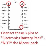
The L293D separates out the 'logic control' and the high current motor circuits internally. It has two different +Ve supply inputs, but in the picture on the Otvinta site, these have both been wired to the same battery pack.
Also, the IC's 'enable' inputs (which are 'logic') are connected to this same battery. To my mind (and I've no practical experience), these three connections should be wired to the 'left-hand' side i.e. Electronics battery pack. Also, add a 100nF capacitor (i.e. marked 104) across that battery's supply connections.
 or pictorially ...
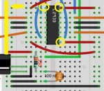
I updated my Test Program to include "Reverse", but it's getting a bit long to easily cut-and-paste off the screen, so here it is as an attachment:
...the Test Program cycles through the various options (though I managed to omit Reverse at my 1st attempt) - the fact that the messages are scrolling through the Serial Terminal window is good (because it means the Picaxe isn't crashing and rebooting).
However, the Test Program contains no code to handle the I.R. signals ... so the fact that things are happening randomly is an indication all is not well further down the line. (It's definitely not responding to your button presses, but some other instability in the system!)
Looking at the datasheet for the L293D, everything looks more or less OK, other than something @Hemi345 already pointed out:
The L293D separates out the 'logic control' and the high current motor circuits internally. It has two different +Ve supply inputs, but in the picture on the Otvinta site, these have both been wired to the same battery pack.
Also, the IC's 'enable' inputs (which are 'logic') are connected to this same battery. To my mind (and I've no practical experience), these three connections should be wired to the 'left-hand' side i.e. Electronics battery pack. Also, add a 100nF capacitor (i.e. marked 104) across that battery's supply connections.
or pictorially ...I updated my Test Program to include "Reverse", but it's getting a bit long to easily cut-and-paste off the screen, so here it is as an attachment:
Attachments
-
1.1 KB Views: 1
PhilHornby
Senior Member
I had a go at amending the main control program. It just needs the I.R. code definition section amending to match the actual buttons being used on the Remote Control.
(Untested!)
(Untested!)
Rich (BB code):
;V2 - correct typos!

#PICAXE 20M2                              ;a 14M2 would suffice!
#Terminal 4800
#no_data
;
; Sony Infra Red control codes - change to match keys used on *your* Remote Control
;
symbol Forwards     = 116
symbol Right        = 51
symbol Left         = 52
symbol Stop_tank    = 101
symbol Reverse_tank = 117
;
; Pin definitions
;
symbol L293D_Input1 = C.3                 ;Input 1 on L293D
symbol L293D_Input2 = B.4                 ;guess ;-)
symbol L293D_Input3 = C.2
symbol L293D_Input4 = B.5

symbol IR_Pin       = B.6                 ;I.R. Receiver input
;
; Data definitions
;
symbol IR_code      = b0                  ;code just received
symbol Previous_IR  = b1                  ;previous code received

;
; Start program
;
      Pause 2000                          ;wait 2 seconds for terminal window
      sertxd ("Picaxe booted",cr,lf)
do
      ;
      ;Await a code from the Remote Control
      ;
      irin IR_Pin,IR_Code
      if IR_Code <> Previous_IR then      ;if not a repeat of previous code...
            ;
            ; Act upon code received
            ;
            select case IR_Code

                  case Forwards
                  high L293D_Input1,L293D_Input3
                  low L293D_Input2,L293D_Input4
                  sertxd ("Forwards",cr,lf)

                  case Right
                  high L293D_Input1,L293D_Input4
                  low L293D_Input2,L293D_Input3
                  sertxd ("Right",cr,lf)

                  case Left
                  high L293D_Input2,L293D_Input3
                  low L293D_Input1,L293D_Input4
                  sertxd ("Left",cr,lf)

                  case Stop_Tank
                  low L293D_Input1,L293D_Input2,L293D_Input3,L293D_Input4
                  sertxd ("Stop",cr,lf)

                  case Reverse_Tank
                  high L293D_Input2,L293D_Input4
                  low L293D_Input1,L293D_Input3
                  sertxd ("Reverse",cr,lf)

                  else
                  sertxd ("Unrecognised I.R. code: ",#IR_Code,cr,lf)

            end select

            Previous_IR = IR_Code         ;Remember last I.R. code received.

      endif
loop
Attachments
-
1.7 KB Views: 3
Last edited:
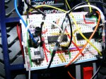
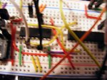
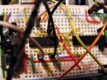
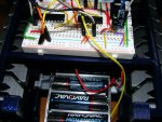
Phil as you can tell by now I don't have a clue as to how this works but if I move them wires over will the motors still be operating on the higher voltage ?.I'm going to add some photos of my B B so you can see what I have wrong.I'm slightly confused ...
...the Test Program cycles through the various options (though I managed to omit Reverse at my 1st attempt) - the fact that the messages are scrolling through the Serial Terminal window is good (because it means the Picaxe isn't crashing and rebooting).
However, the Test Program contains no code to handle the I.R. signals ... so the fact that things are happening randomly is an indication all is not well further down the line. (It's definitely not responding to your button presses, but some other instability in the system!)
Looking at the datasheet for the L293D, everything looks more or less OK, other than something @Hemi345 already pointed out:
The L293D separates out the 'logic control' and the high current motor circuits internally. It has two different +Ve supply inputs, but in the picture on the Otvinta site, these have both been wired to the same battery pack.
Also, the IC's 'enable' inputs (which are 'logic') are connected to this same battery. To my mind (and I've no practical experience), these three connections should be wired to the 'left-hand' side i.e. Electronics battery pack. Also, add a 100nF capacitor (i.e. marked 104) across that battery's supply connections.
View attachment 22533 or pictorially ...View attachment 22537
I updated my Test Program to include "Reverse", but it's getting a bit long to easily cut-and-paste off the screen, so here it is as an attachment:
Attachments
-
 799.6 KB Views: 10
 -
 774.8 KB Views: 9
 -
 795.2 KB Views: 8
 -
 822.4 KB Views: 8
 -
 470.4 KB Views: 9
I also tried your rewrite of the program and the buttons are right when checked in the terminal but the tank don't move.Phil as you can tell by now I don't have a clue as to how this works but if I move them wires over will the motors still be operating on the higher voltage ?.I'm going to add some photos of my B B so you can see what I have wrong.
Hemi345
Senior Member
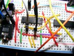
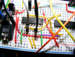
@zneb, I've circled the two enable wires that need to be moved to the logic V+ rail instead of the Motor V+ rail.
I'm not seeing specs on the enable pins in the Ti datasheet. It doesn't indicate what the max voltage, threshold, etc is for the enable pins. But I do see in their test circuit (page 5) that they're using 3V and 0V to test enable functionality while logic (VCC1) is 5V and motor (VCC2) is 24V. So definitely get the enable pins moved over to logic power.
I'm not seeing specs on the enable pins in the Ti datasheet. It doesn't indicate what the max voltage, threshold, etc is for the enable pins. But I do see in their test circuit (page 5) that they're using 3V and 0V to test enable functionality while logic (VCC1) is 5V and motor (VCC2) is 24V. So definitely get the enable pins moved over to logic power.
Hemi345
Senior Member
Also, the green wire in row 15 on the breadboard needs to be moved over to logic V+ as well.
With regards to the PICAXE, I don't see the 10K (R2) or 22K (R1) programming resistors. You really should have a decoupling capacitor near the PICAXE (C1), like 0.1uF / 100nF especially when motors are involved. See schematic below:

With regards to the PICAXE, I don't see the 10K (R2) or 22K (R1) programming resistors. You really should have a decoupling capacitor near the PICAXE (C1), like 0.1uF / 100nF especially when motors are involved. See schematic below:
Last edited:
PhilHornby
Senior Member
Yes, the power for the motors is supplied to Pin 8 of the L293D (or SN754410 as it turns out!). (This is the red wire in Row 22).if I move them wires over will the motors still be operating on the higher voltage ?
I didn't expect it to work any "better" than the original, but it should give you some clues, as to what it's doing.and he said:I also tried your rewrite of the program and the buttons are right when checked in the terminal but the tank don't move.
I also found out one of My Motores was not working ,BROKEN WIRE so that my have been part of issue. I changed the wire s you suggested but didn't try it yet. I'm thinking I should change the Cap and Res as also suggested by another helper .[HEMI345].. I don't want to blow it all up so I don't know what to do first...I also tried your rewrite of the program and the buttons are right when checked in the terminal but the tank don't move.
My opinion onlyI also found out one of My Motores was not working ,BROKEN WIRE so that my have been part of issue. I changed the wire s you suggested but didn't try it yet. I'm thinking I should change the Cap and Res as also suggested by another helper .[HEMI345].. I don't want to blow it all up so I don't know what to do first...
Check you multimeter is working.
Strip the breadboard to zero.
Take a break.. Walk back and DRAW the circuit on graph/squared paper.
Submit it to the experts here and let them guide you further.
e
Hemi345
Senior Member
@zneb, I think you're really close. Just add a capacitor across the + and - on your logic rail (left side of breadboard). In the space between the PIC and the SN754410, (rows 11 thru 14) build the download circuit with the 10K and 22K resistors like the schematic I posted in post #34. Verify your program is using pins B.5,B.4 and C.2,C.3 for controlling the motors (as you had it in the picture I edited) and things should work.
Well thanks to all of you guys It is working now , Batterys are a little low but it all works as it should. Hemi the 10k and 22k were already in there. you probably couldn't see them in My photos. The capacitor is there also ..By changing them 3 wires You and Phill said, and fixing My motor wire it solved the problem. I think the motors should be a litter stronger. ,Because on the carpet the turning is difficult. I'm building a R C tractor with 3D printer now. so I might Be Back...Thank everyone involved I hope I can Return the help someway in the future.